Own power collecting and outputting system for vehicle

An output system, power technology, applied in vehicle components, transportation and packaging, auxiliary drive devices, etc., can solve problems such as no power collection

Inactive Publication Date: 2012-09-05
王 延伟
View PDF0 Cites 0 Cited by
  • Summary
  • Abstract
  • Description
  • Claims
  • Application Information

AI Technical Summary

Problems solved by technology

But there is no such power collection and output system (device) at present

Method used


Image

  • Own power collecting and outputting system for vehicle
  • Own power collecting and outputting system for vehicle
  • Own power collecting and outputting system for vehicle

Examples


Embodiment approach

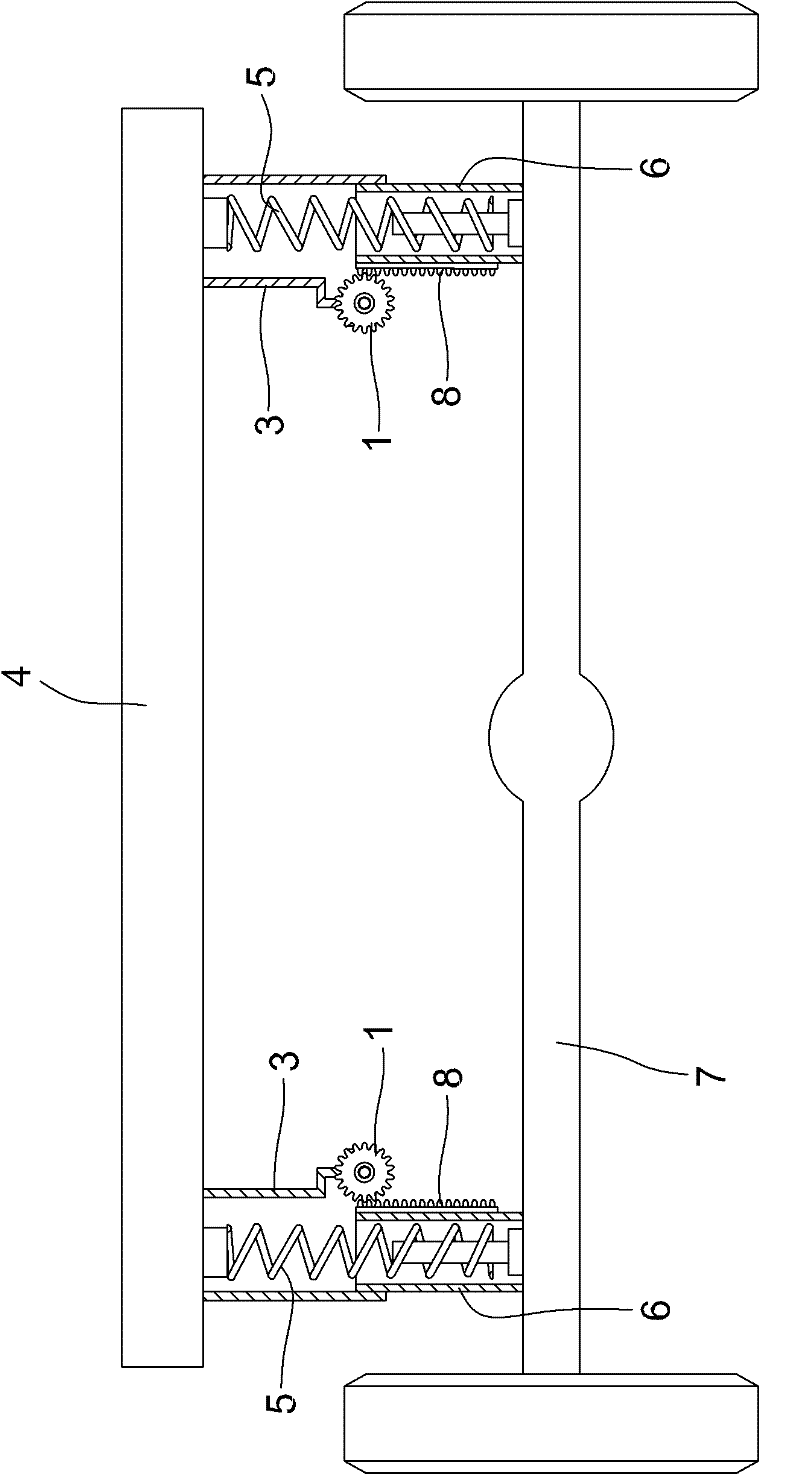
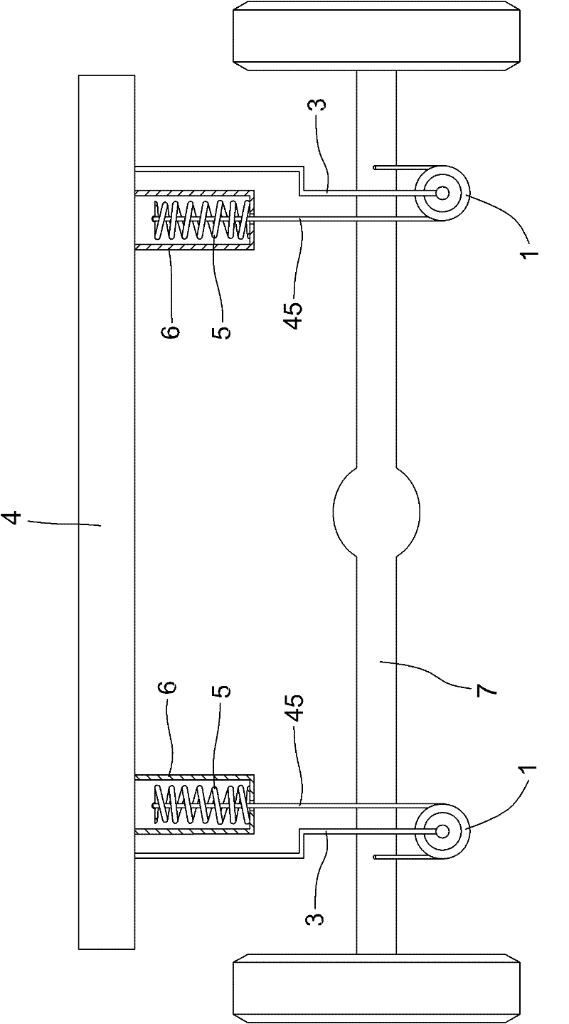
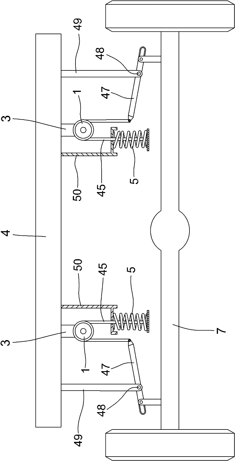
[0054] Please refer to figure 1 , figure 2 , image 3 , Figure 4 , the present invention is a vehicle self-power collection and output system, including a power collection device and an elastic energy storage device, the power collection device is installed between the vehicle chassis and the axle housing, and the power collection device is composed of a transmission mechanism and a primary input wheel , the power collection device has the following three implementations, which are described in detail below:

[0055] Please refer to figure 1 , Figure 4 , in this embodiment, the primary input wheel 1 is made of gears, the primary input wheel 1 is fixedly connected to the primary transmission shaft 10, the primary transmission shaft 10 is supported by the bearing in the bearing seat 19, and the bearing seat 19 is connected to the bracket 3 Above, the bracket 3 is fixedly connected to the vehicle chassis 4, the transmission mechanism is composed of a spring 5 and a rack 8...


PUM


Abstract

The invention relates to an own power collecting and outputting system for a vehicle. The system comprises a power collecting device, a primary transmission shaft, a secondary transmission shaft, a primary flywheel, a secondary flywheel, a second input wheel and an elastic energy storage device, wherein the power collecting device is arranged between a vehicle chassis and an axle housing and consists of a transmission mechanism and a primary input wheel; the primary input wheel is fixedly connected with the primary transmission shaft, and the primary transmission shaft is connected with the primary flywheel; the secondary input wheel is fixedly connected with the secondary transmission shaft; the secondary transmission shaft is connected with the secondary flywheel; the elastic energy storage device comprises a coiled spring, a roller, a shell, an electromagnetic brake, an output gear, an inner insulating ring and an outer insulating ring; the coiled spring is arranged in the roller, and the roller is arranged in the shell; the shell is fixedly connected to the vehicle chassis through a bracket, and the secondary transmission shaft passes through the roller and the shell; the inner end of the coiled spring is fixedly connected to the secondary transmission shaft; and the outer end of the coil spring is fixedly arranged on the inner wall of the roller. The system can be used for collecting power generated by displacement changes between the chassis and the axial housing when the vehicle bumps and outwards outputting the power to do works.

Description

technical field [0001] The invention relates to a power collection and output system of various transportation vehicles. Background technique [0002] As we all know, when the vehicle encounters rough roads during driving, it will appear bumpy. When the vehicle is bumpy, displacement changes will occur between the vehicle chassis (frame) and the front axle housing and rear axle housing to generate power. If this part of power can be collected, it can be exported to do work. But there is no such power collection and output system (device) at present. Contents of the invention [0003] In order to solve the above problems, the object of the present invention is to provide a vehicle self-power collection and output system, which has a novel structure and can fully reduce the displacement between the vehicle chassis (frame) and the front axle housing and rear axle housing when the vehicle is bumping. The power generated during the change is collected and output to the outsid...

Claims


Application Information

Patent Timeline
Patent Type & Authority Patents(China)
IPC IPC(8): B60K25/10B60K17/26
CPCB60K25/10
Inventor 王延伟
Owner 王 延伟
Why Eureka
Try Eureka