A kind of liquid crystal photomask and its application
A photomask and liquid crystal technology, applied in the photomask field, can solve problems such as no application, and achieve the effects of wide application range, high precision controllability, and reduction of environmental pollution
- Summary
- Abstract
- Description
- Claims
- Application Information
AI Technical Summary
Problems solved by technology
Method used
Image

Examples
Embodiment 1
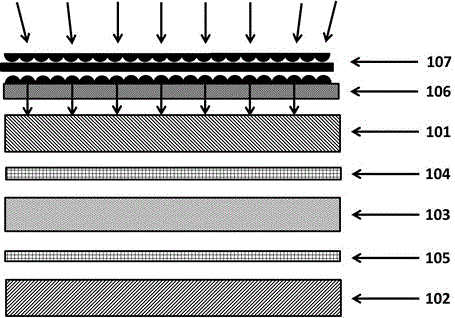
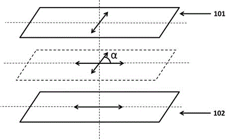
[0029] see figure 1, this specific embodiment 1 provides a liquid crystal photomask, characterized in that the photomask includes an imaging controller (not shown), a light uniform layer 107, a light guide layer 106, a first optical deflection plate 101, a liquid crystal layer 103 and a second optical deflector 102; the liquid crystal layer 103 is sandwiched between the first optical deflector 101 and the second optical deflector 102; the liquid crystal layer 103 is a twisted nematic liquid crystal layer . A first transparent electrode layer 104 is provided on the surface of the first optical deflector 101 in contact with the liquid crystal layer 103 ; a second transparent conductive layer 105 is provided on the surface of the second optical deflector 102 in contact with the liquid crystal layer 103 . The light guide layer 106 organizes the incident light into parallel light, and the parallel light enters the first optical deflection film 101 , and the light guide layer 106 i...
Embodiment 2
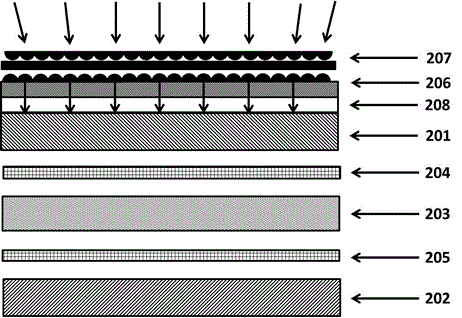
[0037] see image 3 , this specific embodiment 2 provides a kind of liquid crystal photomask, it is characterized in that, described photomask comprises, imaging controller, light homogeneous layer 207, light guiding layer 206, first optical deflection plate 201, liquid crystal layer 203 and the second optical deflector 202; the liquid crystal layer 203 is sandwiched between the first optical deflector 201 and the second optical deflector 202; the liquid crystal layer 203 is a twisted nematic liquid crystal layer. A first transparent electrode layer 204 is arranged on the surface of the first optical deflector 201 in contact with the liquid crystal layer 203; a second transparent conductive layer 205 is arranged on the surface of the second optical deflector 202 in contact with the liquid crystal layer 203; The angle between the polarization direction of the optical deflector 201 and the second optical deflector 202 is 90 degrees; the light guide layer 206 is arranged on the l...
Embodiment 3
[0041] see Figure 4 , this specific embodiment, 3 provides a kind of liquid crystal photomask, it is characterized in that, described photomask comprises, imaging controller, light uniform layer 307, light guide layer 306, first optical deflection film 301, liquid crystal layer 303 and the second optical deflector 302; the liquid crystal layer is sandwiched between the first optical deflector 301 and the second optical deflector 302; the liquid crystal layer 303 is a twisted nematic liquid crystal layer. A first transparent electrode layer 304 is arranged on the surface of the first optical deflector 301 in contact with the liquid crystal layer 303; a second transparent conductive layer 305 is arranged on the surface of the second optical deflector 302 in contact with the liquid crystal layer 303; The angle between the polarization direction of the optical deflector 301 and the second optical deflector 302 is 90 degrees; the light guide layer 306 is arranged on the light inci...
PUM
 Abstract
Description
Claims
Application Information
 - R&D
- Intellectual Property
- Life Sciences
- Materials
- Tech Scout
- Unparalleled Data Quality
- Higher Quality Content
- 60% Fewer Hallucinations
Browse by: Latest US Patents, China's latest patents, Technical Efficacy Thesaurus, Application Domain, Technology Topic, Popular Technical Reports.
© 2025 PatSnap. All rights reserved.Legal|Privacy policy|Modern Slavery Act Transparency Statement|Sitemap|About US| Contact US: help@patsnap.com