
Method and equipment for manufacturing optical fiber perform rod casing pipe with complicated refractive index profile

A technology of refractive index profile and optical fiber preform, which is applied in glass manufacturing equipment, manufacturing tools, etc., can solve the problems of single refractive index of optical fiber preform sleeve, and achieve the requirements of low raw material purity, high deposition rate, and improved manufacturing efficiency. Effect

Active Publication Date: 2014-07-30
ZHONGTIAN TECH ADVANCED MATERIALS CO LTD
View PDF7 Cites 13 Cited by
  • Summary
  • Abstract
  • Description
  • Claims
  • Application Information

AI Technical Summary

Problems solved by technology

[0005] The invention solves the problem that the existing optical fiber preform sleeve only has a single refractive index

Method used


Image

  • Method and equipment for manufacturing optical fiber perform rod casing pipe with complicated refractive index profile
  • Method and equipment for manufacturing optical fiber perform rod casing pipe with complicated refractive index profile
  • Method and equipment for manufacturing optical fiber perform rod casing pipe with complicated refractive index profile

Examples


Embodiment Construction

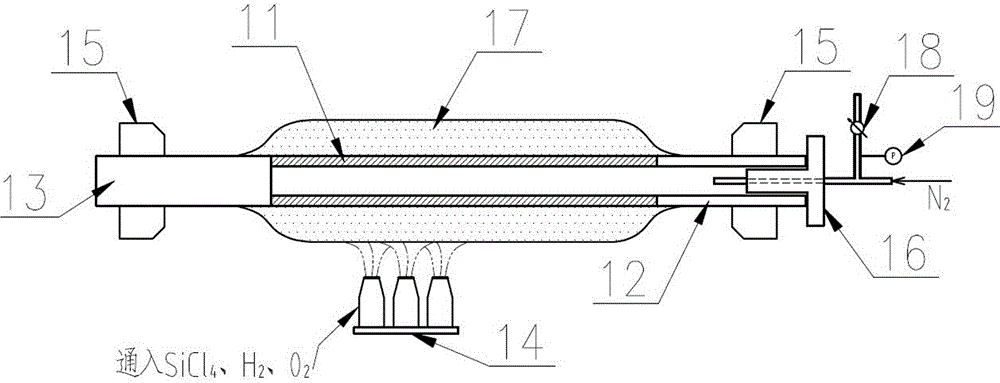
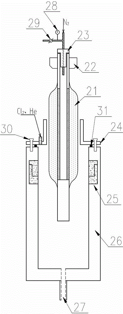
[0037] Refer to attached figure 1 , 2 , a manufacturing equipment for an optical fiber preform sleeve with a complex refractive index profile is composed of a powder sleeve manufacturing device and a powder sleeve vitrification device.

[0038] The powder casing manufacturing device includes a rotary chuck-15, a blowtorch 14, a sealed rotary joint-16, a pressure regulating valve-18 and a pressure gauge-19. One end of the liner 11 is connected with the hollow tailpipe 12, the other end of the liner 11 is connected with the solid tailpipe 13, the solid tailpiece 13 is clamped by the rotary chuck 220, and the hollow tailpipe 12 is clamped by the rotary chuck 15 (target tube), the hollow end of the hollow tail tube 12 (target tube) is sealed with a sealed rotary joint 16, and pressure is applied to the tube through the sealed rotary joint 16; the pressure regulating valve 18 is connected with the sealed rotary joint 16 to adjust the Pressure; pressure gauge one 19 is connected w...


PUM


Abstract

The invention relates to a method and equipment for manufacturing an optical fiber perform rod casing pipe with a complicated refractive index profile, and particularly relates to a method and equipment for manufacturing the optical fiber perform rod casing pipe by combination of modified chemical vapor deposition (MCVD) and outside vapor deposition (OVD). The optical fiber perform rod casing pipe manufactured by using the method and the equipment have a deep refractive index sunken zone or the complicated refractive index profile. The equipment comprises a powder casing pipe manufacturing device and a powder casting pipe vitrification device, wherein the powder casing pipe manufacturing device comprises a rotary chuck I, a rotary chuck II, a blow lamp, a sealing rotary joint I, a pressure adjusting valve I and a pressure gauge l, and the powder casting pipe vitrification device comprises a rotary chuck III, a sealing rotary joint II, a sealing cover plate, a fastening bolt, a sealing ring, a furnace body heating zone, a sealing furnace body, an exhaust gas discharge port, a pressure adjusting valve II and a pressure gauge II.

Description

technical field [0001] The present invention relates to a manufacturing method and manufacturing equipment for an optical fiber preform sleeve with a complex refractive index profile, in particular to a method using improved chemical vapor deposition (MCVD) and out-of-tube vapor deposition (OVD) phase Combined with the method for manufacturing an optical fiber preform tube and its manufacturing equipment, the optical fiber preform tube manufactured by using the method and manufacturing equipment may have a deep refractive index depression or a complex refractive index profile. Background technique [0002] With the development of optical fiber preform technology and the continuous expansion of people's communication requirements, the performance of optical fiber preform has been continuously improved. The total synthesis method and the casing method are two mainstream processes for the manufacture of the outer cladding of the optical fiber preform. , the powdered preform is...

Claims


Application Information

Patent Timeline
IPC IPC(8): C03B37/018
Inventor 陈金文徐希凯蒋新力钱本华周慧
Owner ZHONGTIAN TECH ADVANCED MATERIALS CO LTD
Learn More