
Novel cutting machine device

A cutting machine, a new type of technology, applied in the direction of sawing machine, metal sawing equipment, metal processing equipment, etc., can solve the problems of limited output, increased cutting distance, large processing volume, etc., to reduce the synchronization distance, ensure the cutting length, The effect of long service life

Inactive Publication Date: 2014-07-30
SUZHOU TAKESHENG ELECTRONICS SCI & TECH
View PDF8 Cites 18 Cited by
  • Summary
  • Abstract
  • Description
  • Claims
  • Application Information

AI Technical Summary

Problems solved by technology

[0002] For oversized pipes, generally traditional cutting tables use long serrated blades. This pipe cutting process is prone to several problems: 1. The cutting speed is slow, and the cutting distance must be increased; 2. The long serrated blade It cannot be reused, and the loading and unloading time is long; 3. The specifications of long serrated blades are limited, and the supplier is single and the price is too high
The above-mentioned problems not only make the pipe cutting efficiency low, but also the blades are seriously worn and need to be replaced frequently, which increases the production cost. Due to the troublesome replacement of the blades, the production efficiency is low, and because the specifications are small and the price is high, the production cost is further increased. limit the increase in production
At present, the steel pipe cutting machines commonly used by machinery manufacturing enterprises, some cutting machines are not round, cut obliquely, resulting in scrapping, repairing and other problems; when cutting, the standard length and size cannot be customized, so a relatively large hole must be left for each cutting Processing allowance, resulting in large processing volume and high cost

Method used

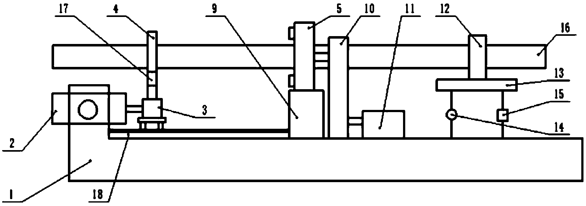

Image

  • Novel cutting machine device
  • Novel cutting machine device
  • Novel cutting machine device

Examples


Embodiment Construction

[0013] The following will clearly and completely describe the technical solutions in the embodiments of the present invention with reference to the accompanying drawings in the embodiments of the present invention. Obviously, the described embodiments are only some, not all, embodiments of the present invention. Based on the embodiments of the present invention, all other embodiments obtained by persons of ordinary skill in the art without making creative efforts belong to the protection scope of the present invention.

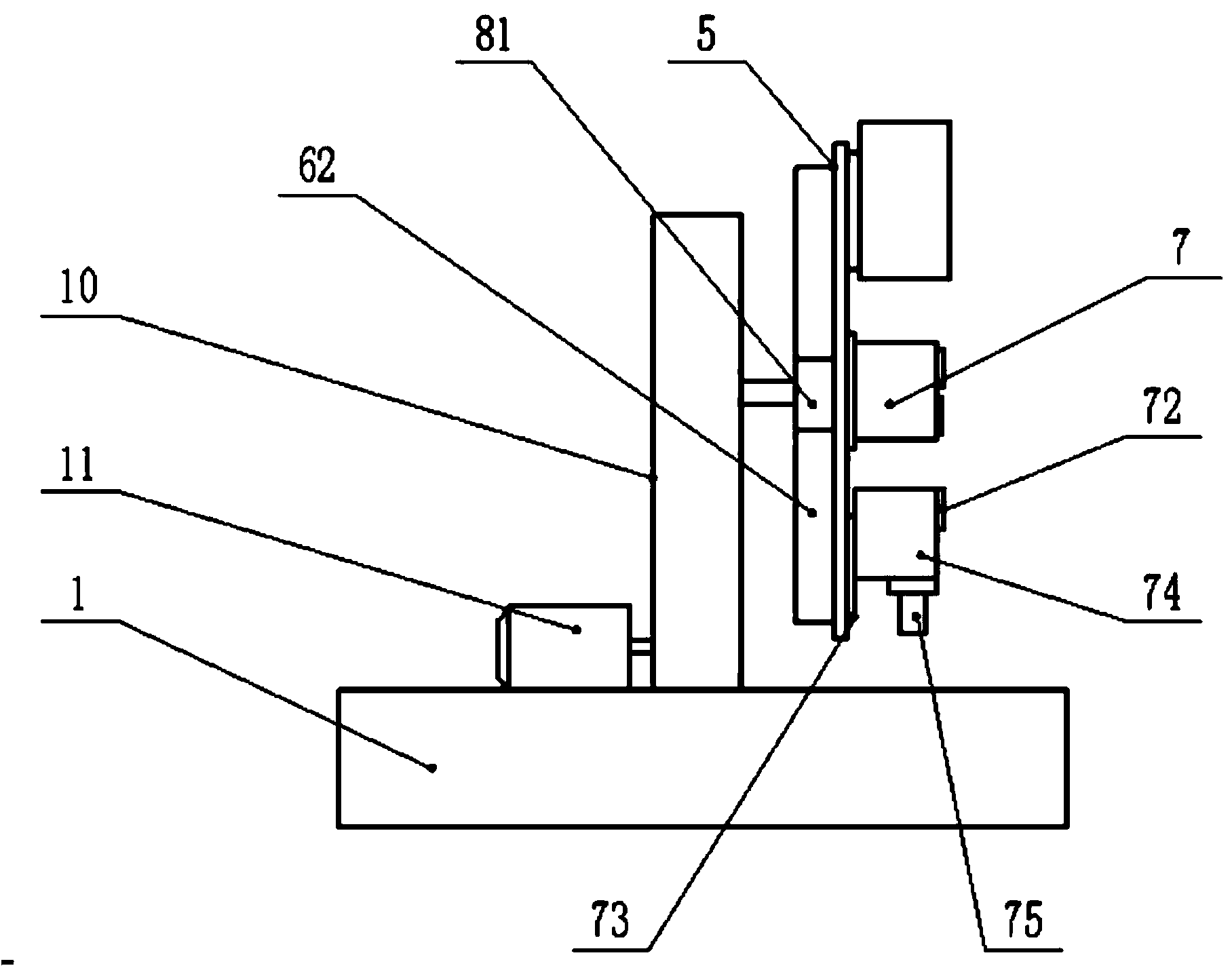
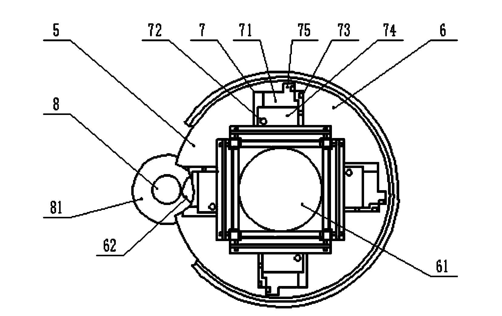
[0014] see Figure 1-3 , in the embodiment of the present invention, a new cutting machine device includes a frame 1; the frame 1 is provided with a cylinder 2 and a slide rail 18; the steel pipe support mechanism 3 connected to the cylinder 2 slides on the slide rail 18 , and the distance is determined by the distance measuring device 17; the steel pipe support mechanism 3 is provided with a locking member 4 for locking the steel pipe 16; the other end of the...


PUM


Abstract

The invention discloses a novel cutting machine device. The novel cutting machine device comprises a frame, wherein a cylinder and a sliding rail are arranged on the frame; a steel tube supporting mechanism connected with the cylinder slides on the sliding rail; a locking component for locking a steel tube is arranged on the steel tube supporting mechanism; a hydraulic motor is arranged on the frame; the hydraulic motor drives a cutter set to rotate through a gearbox; a cutting mechanism is arranged on the outer surface of a circular rotary table on the periphery of a through hole; the cutting mechanism consists of a cutter feeding mechanism and a blade; the blade is arranged at the front end of a cutter holder. Compared with the prior art, the novel cutting machine device has the advantages as follows: the novel cutting machine device improves the cutting efficiency, saves space, is stable in force exerting and easy to control, and ensures the cutting quality; the blade is long in service life, so that the cost is reduced; a steel tube can be adjusted to the required size by the sliding rail for cutting, so that the cutting length is ensured; a height adjusting device can adjust the height and adjust the levelness of a supporting rack and the parallelism of the steel tube.

Description

technical field [0001] The invention is a novel cutting machine device, and specifically relates to the field of cutting machines. Background technique [0002] For oversized pipes, generally traditional cutting tables use long serrated blades. This pipe cutting process is prone to several problems: 1. The cutting speed is slow, and the cutting distance must be increased; 2. The long serrated blade It cannot be reused, and the loading and unloading time is long; 3. The specification of the long serrated blade is limited, and the supplier is single and the price is too high. The above-mentioned problems not only make the pipe cutting efficiency low, but also the blades are seriously worn and need to be replaced frequently, which increases the production cost. Due to the troublesome replacement of the blades, the production efficiency is low, and because the specifications are small and the price is high, the production cost is further increased. limit the increase in product...

Claims


Application Information

Patent Timeline
IPC IPC(8): B23D45/10B23D45/12B23D47/04B23D47/10
Inventor 费志瑾
Owner SUZHOU TAKESHENG ELECTRONICS SCI & TECH
Learn More