
metal bead gasket

A metal bead and gasket technology, applied in the direction of engine sealing, engine sealing device, machine/engine, etc., can solve the problems of complex and expensive machining of the first element 1

Inactive Publication Date: 2017-10-03
BORGWARNER INC
View PDF7 Cites 0 Cited by
  • Summary
  • Abstract
  • Description
  • Claims
  • Application Information

AI Technical Summary

Problems solved by technology

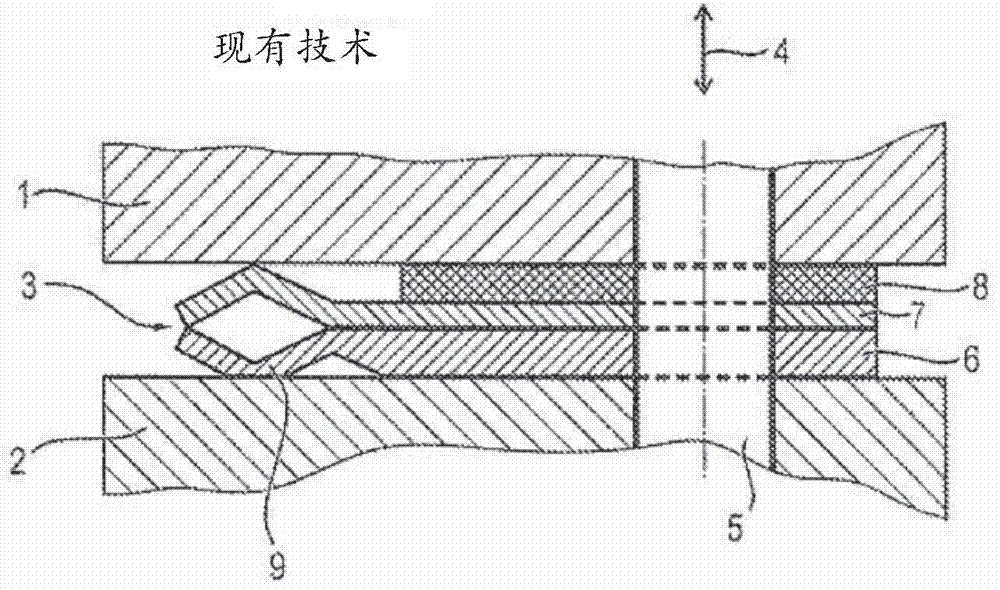
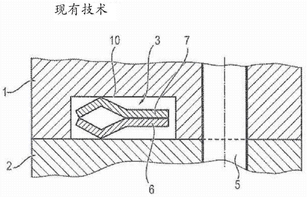
A disadvantage here is that the machining of the first element 1 is complex and expensive due to the milling of the groove 10 into it

Method used


Image

  • metal bead gasket
  • metal bead gasket
  • metal bead gasket

Examples


Embodiment Construction

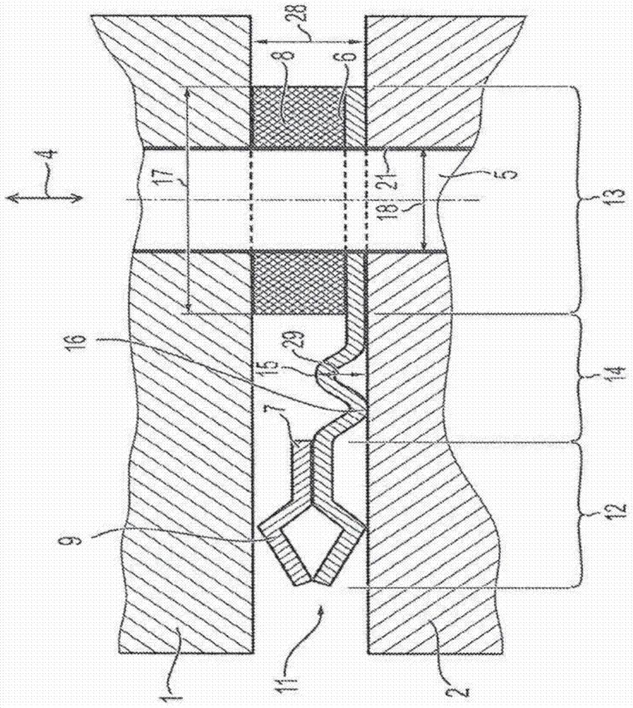
[0025] reference below Figures 3 to 5 Several exemplary embodiments of the present invention are explained in detail.

[0026] image 3 The metal bead gasket 11 is shown in the installed state between a first element 1 and a second element 2 . The metal bead gasket 11 seals the opposing faces of the first and second elements 1, 2 to each other.

[0027] The two elements 1 , 2 are pressed together via a connecting means 5 formed as a screw. The connecting device 5 extends in the supporting direction 4 . A recess 21 formed as a through hole is provided in the metal bead pad 11 . The connection means 5 extend through this recess 21 from the first element 1 to the second element 2 .

[0028] In a direction perpendicular to the supporting direction 4 , the metal bead gasket 11 is divided into a sealing area 12 , a supporting area 13 and an intermediate area 14 . This intermediate region 14 is located between the sealing region 12 and the support region 13 . The sealing area...


PUM


Abstract

The invention relates to a metal bead gasket (11) comprising a sealing area (12) having at least one bead (9); having at least one recess (21) for receiving a support at least one support region (13) of a device (5), in particular a screw; and at least one intermediate region (14) connecting the sealing region (12) to the support region (13), wherein the intermediate region (14) is Configured to be more deformable and less stable perpendicular to the support direction (4) than the sealing area (12) and / or the support area (13).

Description

technical field [0001] The present invention relates to a metal bead gasket and an exhaust turbocharger comprising the metal bead gasket. Background technique [0002] The metal bead gasket works in such a way that the bead pressed into the sealing plate is pressed against the face to be sealed. In this case the contact between the bead and the face to be sealed is virtually linear. Typically, multiple sealing plates are placed one above the other. The corresponding beads of these plates then come into contact with the opposite sealing surface. Beaded plates work due to the prestressing of the beads, which greatly limit their elasticity, even under thermal load. Materials are chosen accordingly. If these beads are pressed to the breaking point, the bead function is lost due to the bead being flattened. To prevent this, metal bead gaskets are usually equipped with a so-called "stop layer". This ensures proper spacing of these sealing faces in the bead area. [0003] f...

Claims


Application Information

Patent Timeline
Patent Type & Authority Patents(China)
IPC IPC(8): F02F11/00F16J15/08
CPCF02F11/002F05D2220/40F16J15/0825F02F11/00
Inventor I·扬图尔
Owner BORGWARNER INC
Learn More