Microwave mode exciting and stirring heating method and heating device thereof
A mode excitation and stirring heating technology, which is applied in the field of microwave mode excitation stirring heating and microwave heating devices, can solve the problems of impossibility, inconvenient rotation or stirring, etc., to improve efficiency, increase the number of electric field modes, and improve uniformity Effect
- Summary
- Abstract
- Description
- Claims
- Application Information
AI Technical Summary
Problems solved by technology
Method used
Image
Examples
Embodiment 1
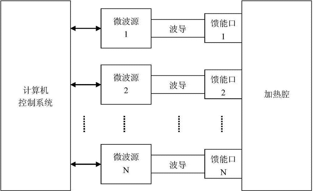
[0031] The structure of the microwave heating device in this example is as follows: figure 1 As shown, it includes a heating cavity, N energy feed ports, N microwave sources and a control system. The microwave energy generated by each microwave source is connected to the corresponding energy feeding port through the waveguide, and the energy is fed to the heating cavity through the energy feeding port. In this example, the control system adopts a computer control system, which is used to control the energy feeding of the heating chamber. In this example, the computer control system divides N energy feed ports into M groups, and feeds energy to the heating chamber in turn, where N and M are positive integers, N≥2, M≥2.
[0032] In this example, N energy feed ports of the microwave heating device are connected to N different microwave sources, and the computer control system can conveniently control the operation of each microwave source, thereby changing the energy feed mode. ...
Embodiment 2
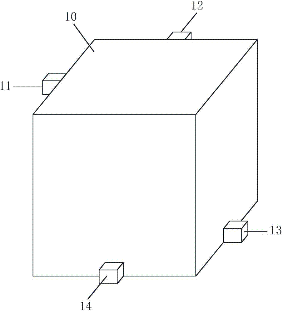
[0036] figure 2 A schematic diagram of the distribution of the heating cavity and the energy feeding port of the microwave heating device of this example is shown. In this example, the heating chamber 10 is a cube, and the energy feeding port 11, the energy feeding port 12, the energy feeding port 13, and the energy feeding port 14 are respectively distributed on the four sides of the heating chamber 10, and the energy feeding port 11 is distributed on the left side of the heating chamber 10. Near the upper edge, the energy feeding ports 13 are distributed on the right side of the heating chamber close to the lower edge, the energy feeding ports 12 are distributed on the back of the heating chamber 10 near the upper edge, and the energy feeding ports 14 are distributed on the front of the heating chamber 10 near the lower edge. The energy feeding mode of the heating chamber 10 in this example can have at least the following types:
[0037] 1. The 4 energy feed ports are divi...
Embodiment 3
[0043] In this example, the heating cavity 10 is spherical, and the energy feeding ports are evenly distributed in the radial direction of the heating cavity 10, image 3 It is a schematic diagram of the distribution of the heating chamber and the energy feeding port of the heating device in this example, and a section of the heating chamber 10 is shown in the figure. This kind of heating cavity can also produce uniform heating effect by controlling the energy feeding of the energy feeding port.
PUM
 Abstract
Description
Claims
Application Information
 - R&D
- Intellectual Property
- Life Sciences
- Materials
- Tech Scout
- Unparalleled Data Quality
- Higher Quality Content
- 60% Fewer Hallucinations
Browse by: Latest US Patents, China's latest patents, Technical Efficacy Thesaurus, Application Domain, Technology Topic, Popular Technical Reports.
© 2025 PatSnap. All rights reserved.Legal|Privacy policy|Modern Slavery Act Transparency Statement|Sitemap|About US| Contact US: help@patsnap.com


