
Self-adaptation frequency hopping pattern generation method

A technology of frequency hopping patterns and generation methods, which is applied to electrical components, transmission systems, etc., can solve the problems of ensuring the orthogonality or quasi-orthogonality of different pseudo-random sequences, exhaustive search is not feasible, and overlapping or collision of hopping frequencies And other issues

Inactive Publication Date: 2014-07-23
UNIV OF ELECTRONICS SCI & TECH OF CHINA +1
View PDF4 Cites 31 Cited by
  • Summary
  • Abstract
  • Description
  • Claims
  • Application Information

AI Technical Summary

Problems solved by technology

The former is easy to implement, such as m-sequence, M-sequence, Gold sequence, etc. are realized by linear shifters. In order to generate pseudo-random sequences with longer periods, linear shift registers with more stages are used; the latter uses nonlinear functions The generator obtains a pseudo-random sequence, but it is difficult to guarantee the orthogonality or quasi-orthogonality between different pseudo-random sequences, that is, it is easy to cause overlapping or collision problems between frequency hopping stations in the frequency hopping network, so most of the current Still using a linear generator
[0005] However, the characteristics and sequence structure of these sequences have been very mature research results, and its structure is easy to crack, that is, the enemy can construct all the sequences for matching search, but it is very difficult to actually crack, because: ① The random sequence corresponding to the frequency hopping pattern can be one of all sequences, and the size of the code space makes this exhaustive search infeasible. ② Even if the sequence used is known, the phase tracking of the frequency hopping pattern is in the It is also difficult in the case of very long pattern periods (up to the order of years)

Method used

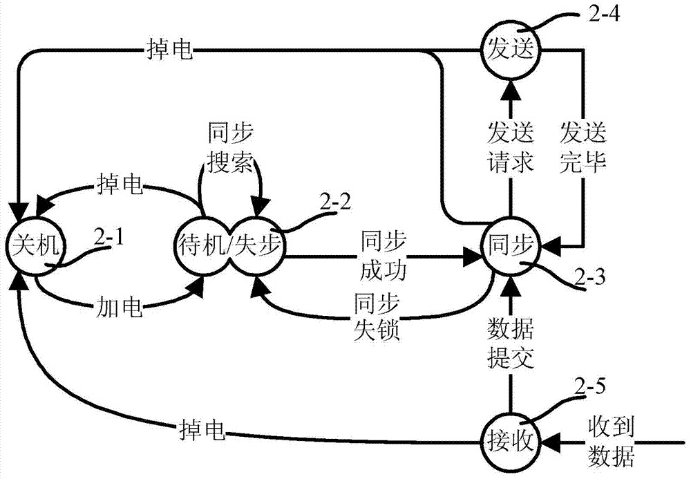
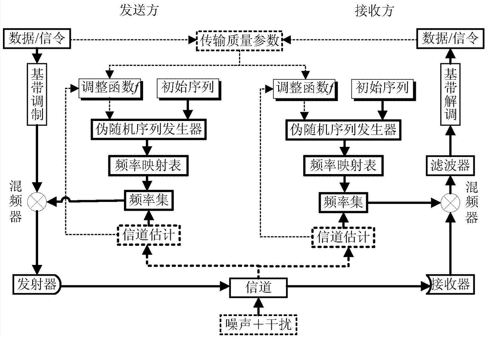
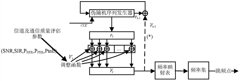

Image

  • Self-adaptation frequency hopping pattern generation method
  • Self-adaptation frequency hopping pattern generation method
  • Self-adaptation frequency hopping pattern generation method

Examples


Embodiment Construction

[0018] Specific embodiments of the present invention will be described below in conjunction with the accompanying drawings, so that those skilled in the art can better understand the present invention. It should be noted that in the following description, when detailed descriptions of known functions and designs may dilute the main content of the present invention, these descriptions will be omitted here.

[0019] The generation method of the adaptive frequency hopping pattern of the present invention introduces a synchronous control mechanism based on channel characteristics on the basis of the existing frequency hopping pattern generation method, and self-adaptively generates the frequency hopping pattern. The synchronous control refers to a process and a method for the communication parties to cooperate to form a consistent frequency hopping pattern.

[0020] As we all know, frequency hopping communication (FH, Frequency Hopping), as a spread spectrum communication method (...


PUM


Abstract

The invention discloses a self-adaptation frequency hopping pattern generation method. Both parties of communication obtain the same SNR and the same SIR through channel estimation, an adjustment factor Vt of a frequency hopping pattern is generated, an operation is performed on the adjustment factor Vt and a frequency hopping pattern control word rt generated by a pseudorandom sequence generator to obtain a frequency hopping pattern control word t, and the frequency hopping pattern control word t is used for generating the frequency hopping pattern. In the self-adaptation frequency hopping pattern generation method, channel estimation is used for generating the self-adaptation frequency hopping pattern based on channel dynamism, the channel dynamism utilized by the self-adaptation frequency hopping pattern is the special characteristic of the both parties of communication, any third party cannot copy the characteristic, and the interception resisting performance is further improved. More importantly, even if one device is cracked or obtained by the enemy, effective interception and interference cannot be performed.

Description

technical field [0001] The invention belongs to the technical field of wireless communication, and more specifically relates to a method for generating an adaptive frequency hopping pattern in a frequency hopping communication system. Background technique [0002] Hopping communication is a spread spectrum communication technology. It divides the communication frequency band into several narrowband sub-channels, and uses the center frequency of the sub-channels to identify these sub-channels. In the communication, the channels corresponding to these frequency points are randomly selected, that is, the period Therefore, it is called frequency hopping communication. Because of its random hopping of instantaneous operating frequency points, it has the advantages of anti-interference and anti-interception, and is widely used in communication fields that require confidentiality. . [0003] The key technologies in frequency hopping communication include frequency hopping synchron...

Claims


Application Information

Patent Timeline
Patent Type & Authority Applications(China)
IPC IPC(8): H04B1/713
Inventor 邝育军顾杰杨峰易翔赵贤李鹏程
Owner UNIV OF ELECTRONICS SCI & TECH OF CHINA
Learn More