Water level signal device for high-position pool

A signal device and pool technology, applied in the direction of buoy liquid level indicator, etc., can solve the problems of water and electricity waste, unable to know the telemetry signal device in time, high water consumption, pool water level, no water in the pool and overflow of the pool.

Inactive Publication Date: 2014-07-23
CHENGDU WANJIANGGANGLI TECH
View PDF4 Cites 7 Cited by
  • Summary
  • Abstract
  • Description
  • Claims
  • Application Information

AI Technical Summary

Problems solved by technology

[0003] Gravity and constant pressure water supply from high-level pools is currently used in many rural centralized water supply stations in hills and mountainous areas. The distance between high-level pools and water supply stations is several kilometers away, and the distance is tens of kilometers. Time, due to the uncertainty of water consumption, the real situation that the operator at the low level or the control system cannot obtain the water level of the high level pool is prone to no water in the pool and overflowing water in the pool; Measure the water level information, and then transmit the water level information to the low-level water level indicator or pumping control device through SMS, radio, and communication lines), and the operator or control system at the low-level pumping control point (usually located near the pump) can obtain high-level The real situation of the water level of the pool, but the water level gauge in the telemetry device, the signal transmission equipment, and the power supply used by these devices have failed (hills and mountainous high-level pools are in harsher environments: lightning strikes, storms, unstable power supply, more prone to failure), resulting in misreporting of the received test data of the water level gauge, the high-level pool will overflow with water, and the operator or the pumping control device at the low-level pumping control point (usually located near the pumping machine) will not be able to know in time that the telemetry signal device has occurred. failure, resulting in serious waste of water and electricity

Method used


Image

  • Water level signal device for high-position pool
  • Water level signal device for high-position pool
  • Water level signal device for high-position pool

Examples


Embodiment 1

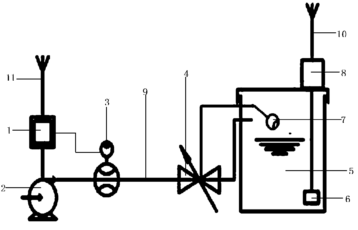
[0020] Embodiment 1: A water level signal device for a high-level pool, comprising a suction pipe 9, a high-level pool 5 and a water pump 2, one end of the water-drawing tube 9 is a water outlet, and the other end is a water inlet, and the water outlet of the suction pipe 9 is connected to the high-level pool 5 , the water inlet of the suction pipe 9 communicates with the water outlet of the water pump 2, and the electromagnetic flowmeter 3 and the ball float valve 4 are installed on the water pipe 9; the installation position of the electromagnetic flowmeter 3 is close to the water inlet of the water pipe 9, the ball float valve 4 The installation position is close to the water outlet of suction pipe 9.

[0021] The floating ball 7 of the floating ball valve 4 described in this embodiment is located in the high-level pool 5; the floating ball valve 4 is located at one end of the high-level pool 5 (that is, the suction pipe 9 where the float valve 4 is installed is close to the...

Embodiment 2

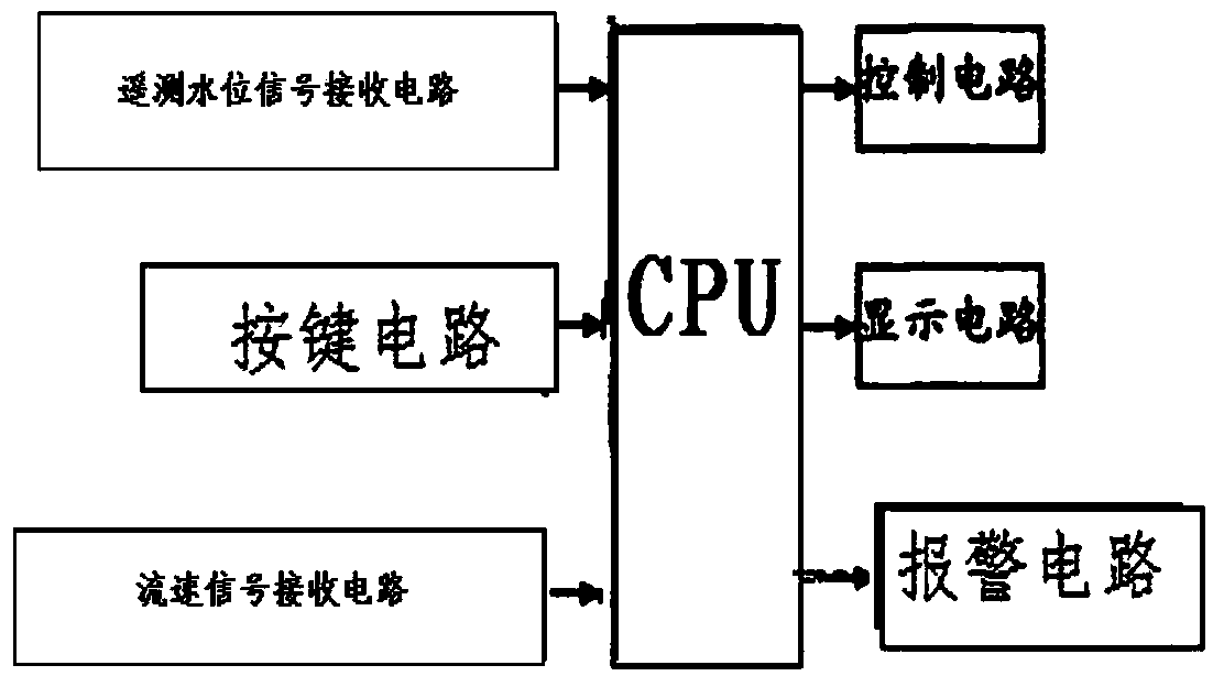
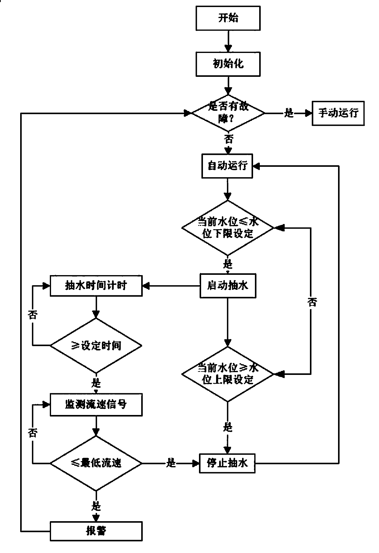
[0024] Embodiment 2: The basic structure of this embodiment is the same as that of Embodiment 1, the difference is that: the device includes a pumping control device 1, and the pumping control device 1 receives the flow velocity signal of the water in the pumping pipe 9 from the electromagnetic flowmeter 3 [ The flow data line of the electromagnetic flowmeter 3 is connected to the pumping control device 1 (specifically connected to the data receiving and processing device of the pumping control device 1)].

Embodiment 3

[0025] Embodiment 3: The basic structure of this embodiment is the same as that of Embodiment 2. The difference is that the device includes a water level telemetry device 8, a signal transmission device 10, and a signal receiving device 11. The signal receiving device 11 is connected to the pumping control device 1, and the water level telemetry Device 8 is connected with signal transmission device 10, and signal transmission device 10 is wirelessly connected with signal receiving device 11, and water level telemetering device 8 passes the water level signal in the high level pool that the water level gauge 6 of water level telemetry device measures through signal transmission device 10, signal receiving The device 11 transmits to the pumping control device 1 .

[0026] The above pumping control device 1 is mainly a PLC control system.

[0027] The above-mentioned water level telemetry device 8 is located at the location of the high level pool 5 , and the water level gauge 6 ...


PUM


Abstract

A water level signal device for a high-position pool comprises a water pumping pipe 9, the high-position pool 5 and a water pump 2, wherein a water outlet is formed in one end of the water pumping pipe 9, a water inlet is formed in the other end of the water pumping pipe 9, the water outlet of the water pumping pipe 9 is communicated with the high-position pool 5, the water inlet of the water pumping pipe 9 is communicated with a water outlet of the water pump 2, and an electromagnetic flowmeter 3 and a float valve 4 are arranged on the water pumping pipe 9. The electromagnetic flowmeter 3 is arranged close to the water inlet of the water pumping pipe 9, and the float valve 4 is arranged close to the water outlet of the water pumping pipe 9. When water in the high-position pool 5 rises to the predetermined position, a floating ball drives the float valve to be closed, water outlet quantity of the water outlet of the water pumping pipe decreases, and flow velocity measured by the electromagnetic flowmeter decreases. Therefore, whether water in the high-position pool rises to the predetermined position can be judged according to changes of water flow velocity measured by the electromagnetic flowmeter 3 at a water pumping control point at a lower position, and users can stop pumping water to prevent water from overflowing out of the high-position pool. The water level signal device for the high-position pool can be matched with water level telemetering devices to find faults of the water level telemetering devices in time.

Description

Technical field [0001] The invention relates to a remote signal device for overflowing water level of high-level pools, especially a water-level signal for high-level pools under the circumstances that the high-level pools of rural centralized water supply stations are far away from water plants, it is difficult to lay signal lines, the power supply is unstable, and environmental factors are bad. device. Background technique [0002] The high-level pool gravity constant pressure water supply method is widely used, especially in hills and mountainous areas. Rural centralized water supply stations mostly use the high-level pool gravity constant pressure water supply method to supply users, that is, select a suitable high point in the water supply area to build a reservoir. The station transports the tap water to the high-level pool for storage through the water pump, and the high-level pool is transported to the user by means of gravity and constant pressure. This water suppl...

Claims


Application Information

Patent Timeline
Patent Type & Authority Applications(China)
IPC IPC(8): G01F23/30
Inventor 古钟璧贺新李中志曹雨肖廷亭杨宇文艺杰
Owner CHENGDU WANJIANGGANGLI TECH
Why Eureka
Try Eureka