
Hydraulic return travel radial plunger pump adopting double-column slide valves for oil distribution

A radial column and plunger technology, which is applied to the components of the pumping device for elastic fluids, pumps, multi-cylinder pumps, etc., can solve the problems of high processing difficulty of the distribution shaft, unreliable return speed, and difficult to achieve sealing. , to achieve the effect of compact structure, low noise and convenient maintenance

Inactive Publication Date: 2014-07-23
XI AN JIAOTONG UNIV
View PDF6 Cites 13 Cited by
  • Summary
  • Abstract
  • Description
  • Claims
  • Application Information

AI Technical Summary

Problems solved by technology

In the existing radial piston pump, the oil distribution method is mostly one-way valve oil distribution or shaft oil distribution. Spring parts are needed in the one-way valve oil distribution method. Since the spring needs to be deformed frequently during the working process, the Fatigue damage is prone to occur, and the noise and vibration are large during operation; while the hydraulic pump with shaft oil distribution, the distribution shaft is difficult to process, and it is not easy to achieve good sealing
In addition, in the existing radial piston pumps, the return stroke of the plunger generally relies on centrifugal force or spring force, etc. For the method relying on centrifugal force, there are disadvantages of unreliable return speed and poor oil absorption capacity. Like the spring in the valve, it also has the disadvantage of being prone to fatigue damage

Method used


Image

  • Hydraulic return travel radial plunger pump adopting double-column slide valves for oil distribution
  • Hydraulic return travel radial plunger pump adopting double-column slide valves for oil distribution
  • Hydraulic return travel radial plunger pump adopting double-column slide valves for oil distribution

Examples


Embodiment Construction

[0026] The present invention will be described in detail below in conjunction with the accompanying drawings.

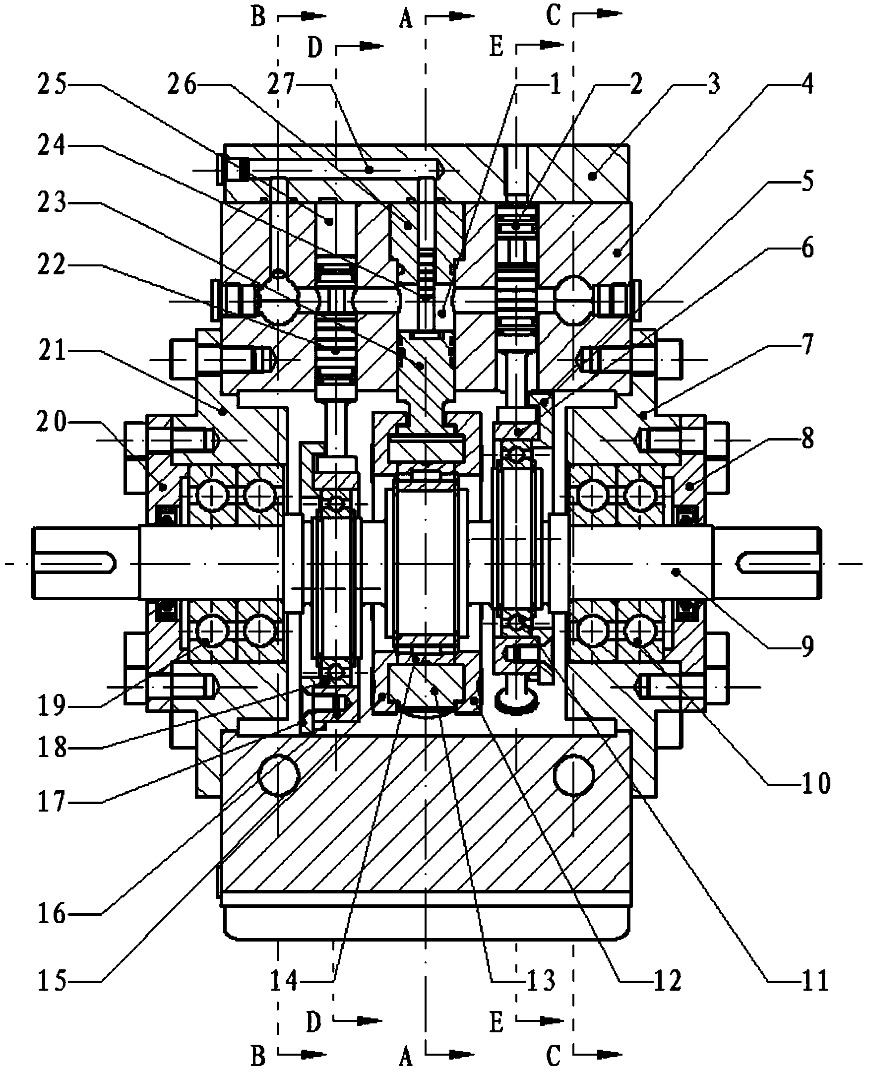
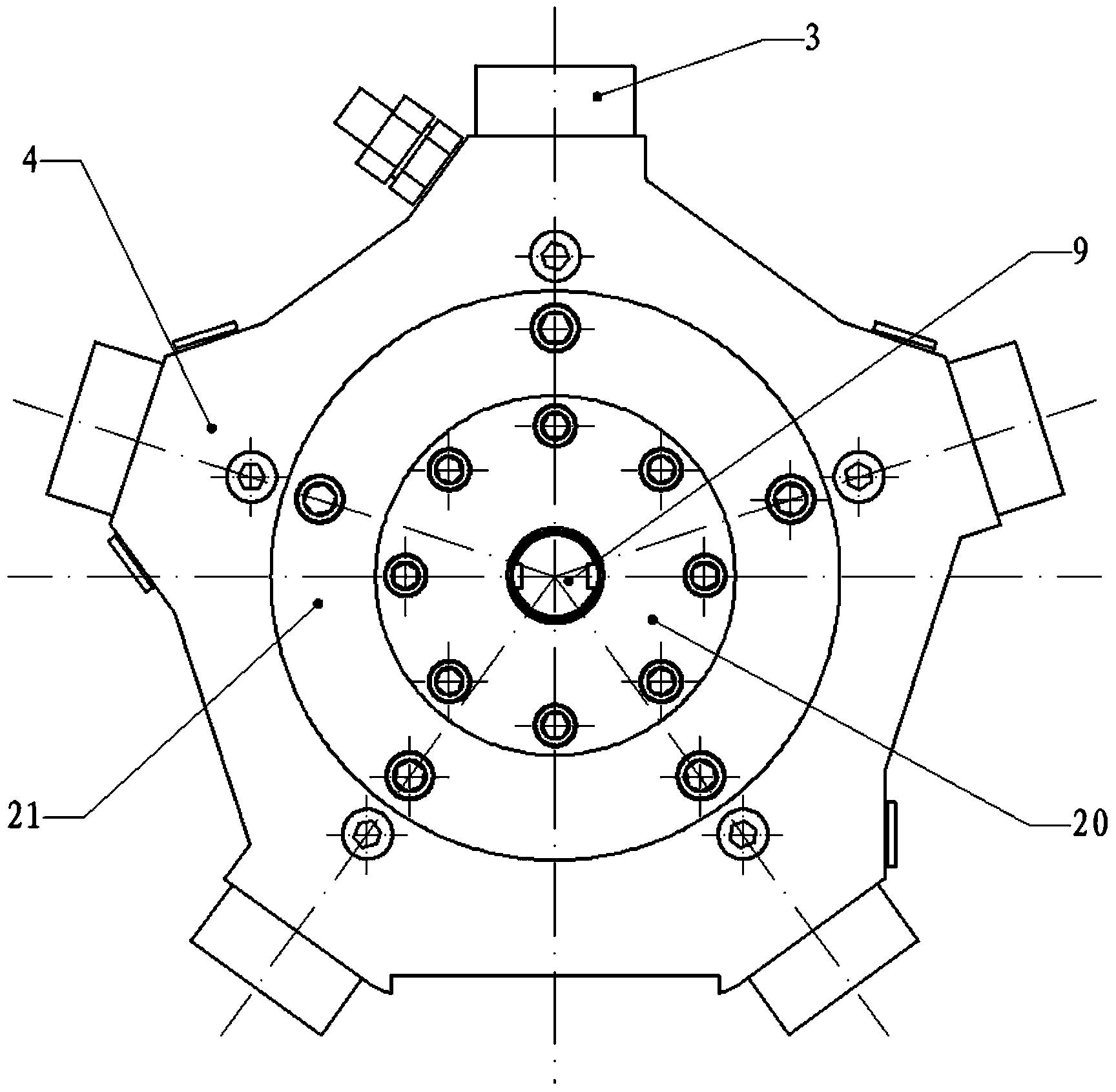
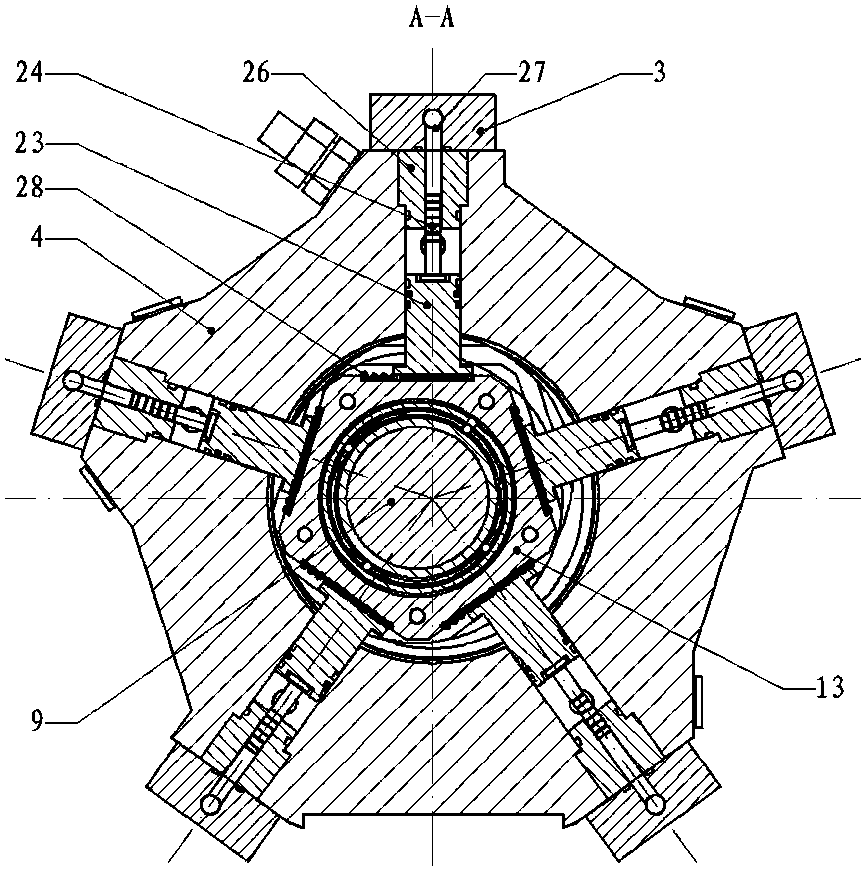
[0027] refer to figure 1 , figure 2 and image 3 , a hydraulic return radial piston pump adopting double-row sliding valve oil distribution, including a pump body 4, five plunger groups 37 are installed on the pump body 4, and the five plunger groups 37 are evenly distributed in the radial direction On the same plane, each plunger group 37 includes a plunger 23, a plunger return guide post 24, a plunger return guide sleeve 26, and a plunger gland 3. One end of the plunger return guide post 24 abuts against the plunger 23, and the other One end is inserted into the plunger return guide sleeve 26, and moves axially with the plunger 23, the plunger 23 and the plunger return guide sleeve 26 are inserted into the plunger hole 1 on the pump body 4, and the plunger gland 3 passes through The screw is installed on the pump body 4, and the plunger return guide sleeve 26 i...


PUM


Abstract

Provided is a hydraulic return travel radial plunger pump adopting double-column slide valves for oil distribution. Five plunger sets are arranged in the radial direction, the flow distribution slide valves matched with the plunger sets in work are arranged abreast on the two sides of plungers, the communication of oil feeding and oil discharging is achieved through an oil discharging and collecting flow channel and an oil feeding and collecting flow channel which are formed in a pump body, the space in the pump body is fully utilized, the rotation of a transmission shaft is converted into the needed rectilinear motion through a pentagon and corresponding bearings, transmission is reliable, and friction force is small. Due to the fact that hydraulic force is utilized in return travel, the return travel force is stable, noise is small, and the service life is long. Due to the fact that thrust is transmitted to the plungers through quill rollers, the friction force between relative moving surfaces is lowered. Due to the fact that the plunger sets are mounted on the pump body from the exterior through screws, fast demounting can be achieved, and mounting and maintaining are convenient.

Description

technical field [0001] The invention belongs to the technical field of radial plunger pumps, and in particular relates to a hydraulic return radial plunger pump adopting double row slide valves for oil distribution. Background technique [0002] Radial piston pump is a kind of positive displacement hydraulic pump in which the plunger is arranged radially along the pump body. It has the advantages of large displacement, high pressure, and low wear. It is often used in hydraulic systems in forging, exploration and other fields. In the existing radial piston pump, the oil distribution method is mostly one-way valve oil distribution or shaft oil distribution. Spring parts are needed in the one-way valve oil distribution method. Since the spring needs to be deformed frequently during the working process, the Fatigue damage is prone to occur, and the noise and vibration during operation are relatively large; while the hydraulic pump using shaft oil distribution, the processing of ...

Claims


Application Information

Patent Timeline
IPC IPC(8): F04B1/047F04B53/10
Inventor 赵升吨郭桐李靖祥刘辰韩晓兰张晨阳张琦
Owner XI AN JIAOTONG UNIV
Learn More