
Gas deduster

A dust collector and gas technology, applied in the field of dust removal equipment, can solve the problems of high filter bag replacement cost, dust escape and high pressure resistance, and achieve the effect of reducing the replacement cost of spare parts, avoiding secondary pollution and overcoming dust escape.

Inactive Publication Date: 2014-07-23
任利萍
View PDF0 Cites 5 Cited by
  • Summary
  • Abstract
  • Description
  • Claims
  • Application Information

AI Technical Summary

Problems solved by technology

[0002] At present, industrial dust is one of the pollution sources of the atmospheric environment. Traditional electrostatic precipitators and bag filters are widely used in the field of gas dust removal, but they have the following deficiencies: 1. The traditional electrostatic precipitators are not ideal for collecting fine dust. The gas flow rate in the dust removal chamber exceeds the design value, which can easily cause dust to escape and cause excessive emissions.
2. Although the bag filter has good dust collection effect, it has the disadvantages of high filter bag replacement cost and high pressure resistance, resulting in high operation and maintenance costs for users

Method used


Image

  • Gas deduster
  • Gas deduster
  • Gas deduster

Examples


Embodiment 1

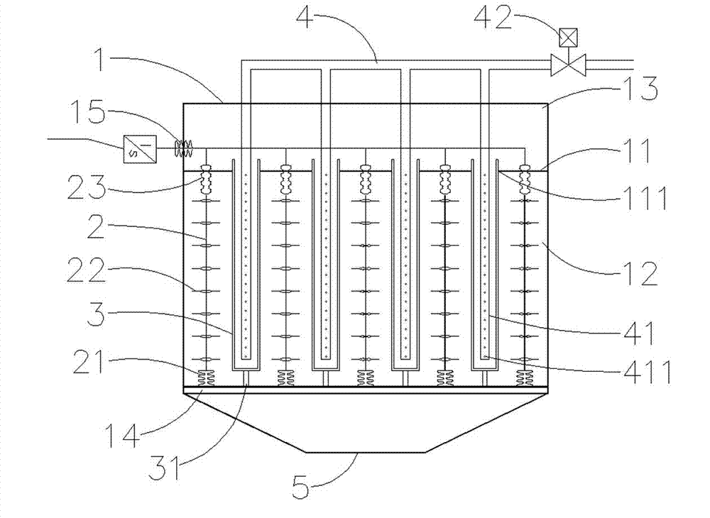
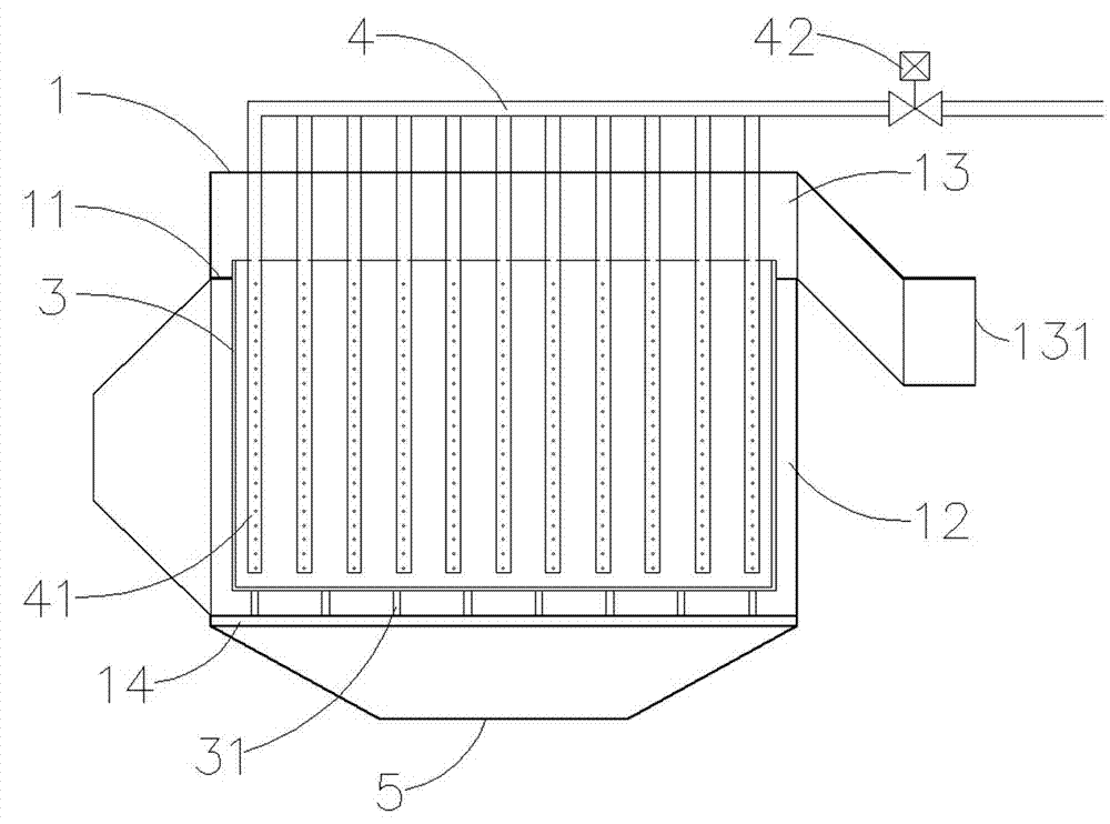
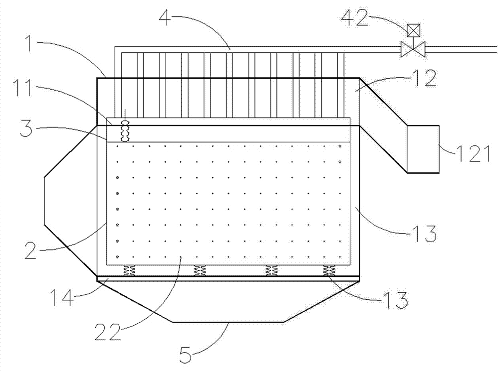
[0033] Embodiment 1: During work, the dusty gas enters the dust removal chamber 12 through the air inlet 121, passes through the high-porosity porous box wall of the dust collection box 3, and the clean gas enters the clean gas chamber 13 from the vent 111 on the partition 11 , and finally flow out from the air outlet 131, while the dust particles stay on the outside of the box wall under the filtering and electrostatic adsorption of the box wall. When the dust particles on the outer wall of the dust collection box 3 are thick, the pressure difference between the inside and outside of the dust collection box 3 increases, the control system starts the electromagnetic control valve 42, and at the same time the power supply of the discharge electrode plate 2 is cut off, and the gap between the discharge electrode plate 2 and the dust collection box 3 The electrostatic field disappears, and the soot blowing pipe 41 ejects high-pressure gas from each air injection hole 411, and blow...

Embodiment 2

[0034] Embodiment 2: When working, turn on the power supply, and the high-voltage direct current with a voltage level of 60000V to 70000V forms a high-voltage electric field through the discharge electrode plate 2, and the surrounding gas is ionized by corona discharge through the metal thorns 22 on the discharge electrode plate 2 to form charged When ions and dust particles in the gas pass through the high-voltage electrostatic field from all around, they collide with the positive and negative ions and electrons between the electrodes and are charged (or charged during the ion diffusion movement), and the dust particles with electrons and ions are charged in the electric field force It moves to the dust collecting box 3 under the action of the action and electrostatic accumulation is attached on the dust collecting box 3.


PUM

PropertyMeasurementUnit
lengthaaaaaaaaaa
thicknessaaaaaaaaaa
thicknessaaaaaaaaaa

Abstract

The invention belongs to the field of dedusting equipment and in particular relates to a gas deduster formed by a high-efficiency dust-collecting body and static electricity through combination. The gas deduster is composed of a shell, a discharge electrode plate, a dust collecting box, a soot blower and a dust hopper, wherein the shell is of a rectangular chamber and is divided into an upper independent gas purification chamber and a lower independent dedusting chamber by a partition plate; more than two vent holes are uniformly formed in the partition plate; a gas inlet is formed in the box wall at the front end of the dedusting chamber, and the bottom of the dedusting chamber opens and is provided with a support beam; a gas outlet is formed in the box wall at the rear end of the gas purification chamber; the discharge electrode plate and the dust collecting box are fixedly arranged in the dedusting chamber and are uniformly arranged at intervals; the soot blower is fixedly arranged on the top plate of the dedusting chamber; the dust hopper is fixedly arranged at the bottom of the dedusting chamber. The gas deduster has the beneficial effects of being simple in structure, improving the dedusting efficiency, preventing secondary gas pollution and reducing the maintaining cost.

Description

technical field [0001] The invention belongs to the field of dust removal equipment, and in particular relates to a gas dust collector which utilizes a high-efficiency dust collector combined with static electricity. Background technique [0002] At present, industrial dust is one of the pollution sources of the atmospheric environment. Traditional electrostatic precipitators and bag filters are widely used in the field of gas dust removal, but they have the following deficiencies: 1. The traditional electrostatic precipitators are not ideal for collecting fine dust. If the gas flow rate in the dust removal chamber exceeds the design value, it is very easy to cause dust to escape and cause the emission to exceed the standard. 2. Although the bag filter has good dust collection effect, it has the disadvantages of high filter bag replacement cost and high pressure resistance, resulting in high operation and maintenance costs for users. Contents of the invention [0...

Claims


Application Information

Patent Timeline
Patent Type & Authority Applications(China)
IPC IPC(8): B01D50/00
Inventor 任利萍
Owner 任利萍
Learn More