
Locking device for spiral groove of anterior cervical steel plate

An anterior cervical approach and locking device technology, applied in the field of medical devices, can solve the problems of difficult cervical vertebrae, unpre-bent treatment of steel plates, and difficulty in completing fixation, etc.

Inactive Publication Date: 2014-07-23
博能华医疗器械(北京)有限公司
View PDF6 Cites 5 Cited by
  • Summary
  • Abstract
  • Description
  • Claims
  • Application Information

AI Technical Summary

Problems solved by technology

The AO locking plate is too wide, with a width of 20.65 mm. It is more difficult to apply it to the higher cervical spine during operation. It is often necessary to cut and push away the longus colli muscle to find the ideal fixation point. Some thin patients are difficult to complete fixation, and The steel plate is not pre-bent treatment is its shortcoming

Method used


Image

  • Locking device for spiral groove of anterior cervical steel plate
  • Locking device for spiral groove of anterior cervical steel plate
  • Locking device for spiral groove of anterior cervical steel plate

Examples


Embodiment Construction

[0022] Combine below figure 1 The present invention is described further:

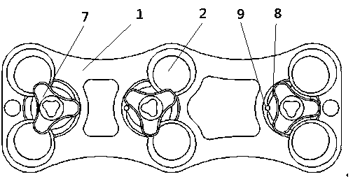
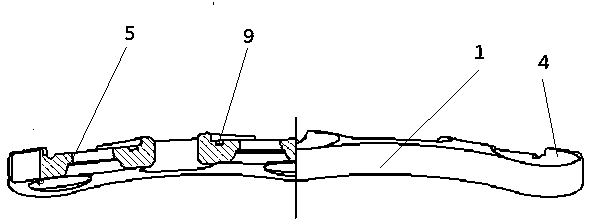
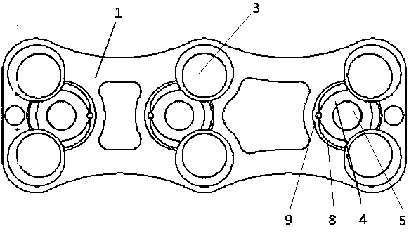
[0023] As shown in the figure, a spiral groove locking device for anterior cervical spine plates includes anterior cervical spine plate 1 and plate screws 2. At least the lower end surface of anterior cervical spine plate 1 matches the physiological curvature of the cervical spine. There is a countersunk head plate screw hole 3, and the countersunk head plate screw hole 3 is provided with a plate screw 2, and the upper end surface of the anterior cervical plate on the side of the countersunk head plate screw hole 3 is provided with a pressure cap groove 4, and the pressure cap groove 4 is provided with The locking hole 5 and the pressing cap groove 4 are provided with a pressing cap 7 with a locking pressing cap sleeve 6, and the end faces of the pressing cap groove 4 and the pressing cap 7 are correspondingly provided with a slideway and a slider 8 that gradually become shallower. 1. Interlocking pi...


PUM


Abstract

The invention discloses a locking device for a spiral groove of an anterior cervical steel plate. The locking device is characterized in that at least the lower end face of the anterior cervical steel plate is matched with the physiological curvature of the cervical vertebra, countersunk steel plate screw holes are formed in the anterior cervical steel plate, pressing cap grooves are formed in the upper end faces of the positions, on ones sides of the countersunk steel plate screw holes, of the anterior cervical steel plate, locking holes are formed in the pressing cap grooves, pressing caps with locking pressing cap sleeves are arranged in the pressing cap grooves, sliding channels becoming light from deep gradually, sliding blocks, concave pits and protrusions are correspondingly arranged on the end faces, in contact with the pressing caps, of the pressing cap grooves, the concave pits and the protrusions are locked, and locating pressing handles for locating steel plate screws in the countersunk steel plate screw holes are arranged on the pressing caps. When the locking device is used, the steel plate is attached to the diseased position of the cervical vertebra, the steel plate is fixed through the screws, the pressing cap are pressed into the pressing cap groove locking holes in a sleeved mode, the pressing cap sliding blocks are made to be in the sliding channels in the pressing cap grooves from deep to light by rotating the pressing caps and are locked through the concave pits and the protrusions, then flanges of the pressing caps are in compression fit with the steel plate, and the locking device has the advantages of being easy to operate, good in stability and the like.

Description

technical field [0001] The invention relates to the technical field of medical devices, in particular to an anterior cervical plate fixation device for treating human cervical diseases. Background technique [0002] With the development of cervical surgery, the application of anterior cervical plate in degenerative diseases of cervical spine has gradually increased. At present, the anterior cervical plate has become an internal fixation system widely used to reconstruct the stability of the cervical spine after cervical intervertebral disc and vertebral body resection. The plate acts as a tension band when it is stretched and supports it when it is flexed. It can decompress with the least segment The fusion with the minimum range of motion to ensure the physiological activities of the spine as much as possible and to ensure its clinical effect. Screws are used to lock the plate so that it fits tightly into the vertebral bodies of the spine and enhances spinal stability. Im...

Claims


Application Information

Patent Timeline
Patent Type & Authority Applications(China)
IPC IPC(8): A61B17/70A61B17/80A61B17/86
CPCA61B17/7059A61B17/7007
Inventor 耿润普孙正杰许振山王志勇李华莹
Owner 博能华医疗器械(北京)有限公司
Learn More