
Patsnap Eureka
For R&D, Patsnap Eureka makes reading and utilizing patents & technical documents easy.
Patsnap Eureka AIR
Designed for self-driven R&D workflows. Generate viable solutions, solve complex R&D challenges, empower your innovation with AI.

Patsnap Eureka Materials
Designed for material experts only. Revolutionize your material R&D, from search, analyze, to developing new materials.

TechResearch
Generate reliable direction feasibility study reports for your R&D in just a few steps.

TechSeek
Discover and master advanced knowledge NOW. Basics, ideas, possibilities, all at once.

TechMind
As an expert in R&D Theories, TechMind can generates customized viable solutions instantly.

TechRisk
Analyze your overall solution with one click, know your potential R&D risks in advance.

TechMonitor
Get weekly tech updates, stay abreast of the latest tech innovations and key insights.
Systems and methods for efficient two-phase heat transfer in compressed-air energy storage systems
A technology for compressing storage and energy, applied in fluid pressure actuation system components, open gas positive displacement engine plants, the arrangement of multiple different prime movers in general power plants, etc. The effect of increasing the surface area
- Summary
- Abstract
- Description
- Claims
- Application Information
AI Technical Summary
Problems solved by technology
Method used
Image


Examples
Embodiment Construction
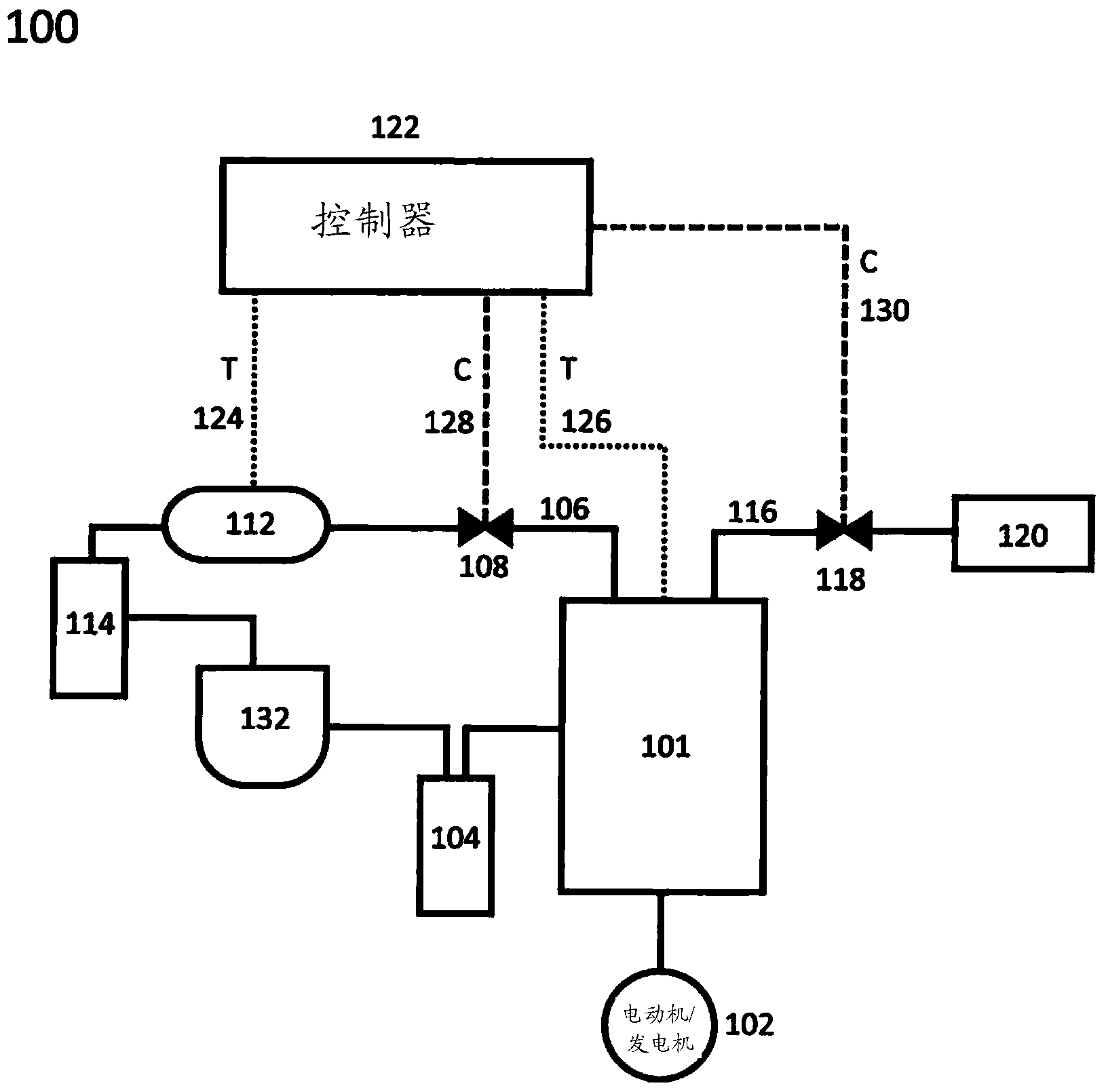
[0168] figure 1 An exemplary system 100 is shown that may be part of a larger system (not shown) for storing and releasing energy. The subsequent figures will illustrate the application of embodiments of the invention to such a system. figure 1 The system 100 shown in FIG. 2 features an assembly 101 for compressing and expanding a gas. Expansion / compression assembly 101 may include or consist essentially of one or more separate devices for expanding or compressing gas (e.g., a turbine or cylinder assembly, each of which may include a movable boundary mechanism ) or graded series of these devices, and figure 1 Auxiliary equipment (e.g. valves) not expressly shown.
[0169] A motor / generator 102 (eg, a rotary or linear motor) is physically connected to the expansion / compression assembly 101 (eg, via a hydraulic pump, piston shaft, or mechanical crankshaft). The motor / generator 102 can be electrically connected to figure 1 Sources and / or sinks of electrical energy not ex...
PUM
 Abstract
Description
Claims
Application Information
 - R&D Engineer
- R&D Manager
- IP Professional
- Industry Leading Data Capabilities
- Powerful AI technology
- Patent DNA Extraction
Browse by: Latest US Patents, China's latest patents, Technical Efficacy Thesaurus, Application Domain, Technology Topic, Popular Technical Reports.
© 2024 PatSnap. All rights reserved.Legal|Privacy policy|Modern Slavery Act Transparency Statement|Sitemap|About US| Contact US: help@patsnap.com