
M-phase permanent magnet motor control method for directly solving pulse width modulation through duty ratios

A pulse width modulation, permanent magnet motor technology, used in motor generator control, AC motor control, electronic commutation motor control, etc. The effect of simplifying complexity

Active Publication Date: 2014-07-16
SOUTHEAST UNIV
View PDF5 Cites 7 Cited by
  • Summary
  • Abstract
  • Description
  • Claims
  • Application Information

AI Technical Summary

Problems solved by technology

The traditional M-phase SVPWM algorithm has sector judgment, complex operation of trigonometric functions and uncontrollable harmonic current

Method used


Image

  • M-phase permanent magnet motor control method for directly solving pulse width modulation through duty ratios
  • M-phase permanent magnet motor control method for directly solving pulse width modulation through duty ratios
  • M-phase permanent magnet motor control method for directly solving pulse width modulation through duty ratios

Examples


Embodiment 1

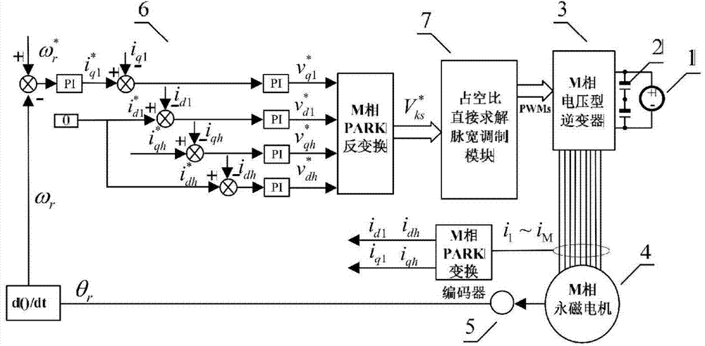
[0033] Embodiment 1: as figure 1 As shown, when the windings of the M-phase permanent magnet motor are sinusoidally distributed, the duty ratio is used to directly solve the M-phase permanent magnet motor control method of pulse width modulation, through the photoelectric encoder 5, including a speed outer ring and M-1 current The vector control module 6 of the inner loop, the duty ratio direct solution pulse width modulation module 7 and the M-phase voltage type inverter 3 control the M-phase permanent magnet motor 4, including the following specific steps:

[0034] Step 1), in each control cycle, the motor rotor position θ is measured and calculated by the photoelectric encoder 5 r and the actual rotor speed ω r ;

[0035] Step 2), the given speed value of the motor and actual speed ω r After comparison, the quadrature-axis current component of the fundamental wave of the given electromagnetic torque is obtained through the PI regulator of the outer ring of the speed ...

Embodiment 2

[0065] Embodiment 2: When the windings of the M-phase permanent magnet motor are distributed at a concentrated and full distance, the control method of the M-phase permanent magnet motor that directly solves the pulse width modulation by using the duty ratio is based on the sinusoidal power supply, and only needs to combine the harmonic injection rate The motor smoothly transitions from a sinusoidal power supply state to a non-sinusoidal power supply state, while the output torque increases.


PUM


Abstract

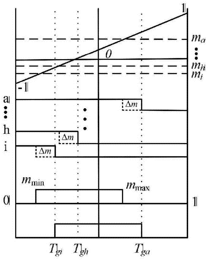
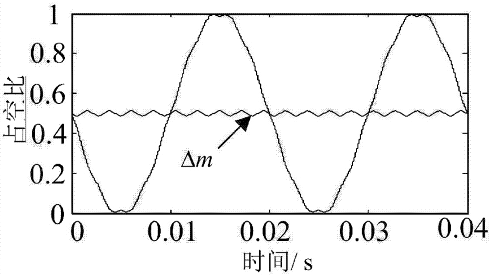
The invention relates to an M-phase permanent magnet motor control method for directly solving pulse width modulation through duty ratios. According to the method, the duty ratios of all bridge arms in a unit sampling period are calculated directly through instantaneous values of reference voltages of all harmonic subspaces of an M-phase system, centralized processing is performed on waveforms of the duty ratios of the bridge arms through interposition of reset factors of the duty ratios, and the trigger time of pulse width modulation signals can be directly solved; the implementation process does not include sector judgment, the whole vector space is seen as a whole, and thus an M-phase space vector pulse width modulation method can be achieved in a digitalized mode easily. All the orthogonal subspace currents are designed in a closed loop and decoupling mode, and thus the defects that according to a traditional space vector pulse width modulation method, the harmonic current of a stator is not controllable and an algorithm is complex are overcome, and the requirement for multi-dimensional space vector control over a multi-phase motor can be met.

Description

technical field [0001] The invention relates to a motor control method for directly solving pulse width modulation by adopting a duty ratio, which can be applied to multi-phase motor speed regulation control applications and belongs to the motor drive technology. Background technique [0002] There are two main ways to achieve high-power speed regulation: multi-level inverter and multi-phase inverter. The former has been widely used in high-voltage occasions in the past ten years; However, most of the research on multi-phase inverters has followed the traditional three-phase two-level related technologies, and has not formed a set of multi-phase own theoretical systems, such as multi-dimensional space decomposition, multi-phase modulation strategy and harmonic Inhibition and other issues, so there is still a lot of research space for multiphase technology. [0003] In multi-phase inverters controlling multi-phase motors, Space Vector Pulse Width Modulation (SVPWM) and Carri...

Claims


Application Information

Patent Timeline
IPC IPC(8): H02P21/14H02P27/06
Inventor 程明於锋花为邹国棠
Owner SOUTHEAST UNIV
Learn More