


Quick Research
Generate reliable direction feasibility study reports for your R&D in just a few steps.

Technical Q&A
Discover and master advanced knowledge NOW. Basics, ideas, possibilities, all at once.

Find Solutions
As an expert in R&D theories, this can generate solutions to your technical problems instantly.

Evaluate Feasibility
Analyze your overall solution with one click, know your potential R&D risks in advance.

Monitor Landscape
Get weekly tech updates, stay abreast of the latest tech innovations and key insights.
Charging and discharging system with adjustable bidirectional currents and voltages of supercapacitor
A supercapacitor, current and voltage technology, applied in battery circuit devices, current collectors, electric vehicles, etc., can solve the problems of inflexible application of supercapacitors and limited use of supercapacitors
- Summary
- Abstract
- Description
- Claims
- Application Information
AI Technical Summary
Problems solved by technology
Method used
Image

Examples
Embodiment 1
[0022] The idea of the present invention is to adjust the input and output voltages of the supercapacitor by using a switchable step-up and step-down circuit, and then charge and discharge the supercapacitor stably.
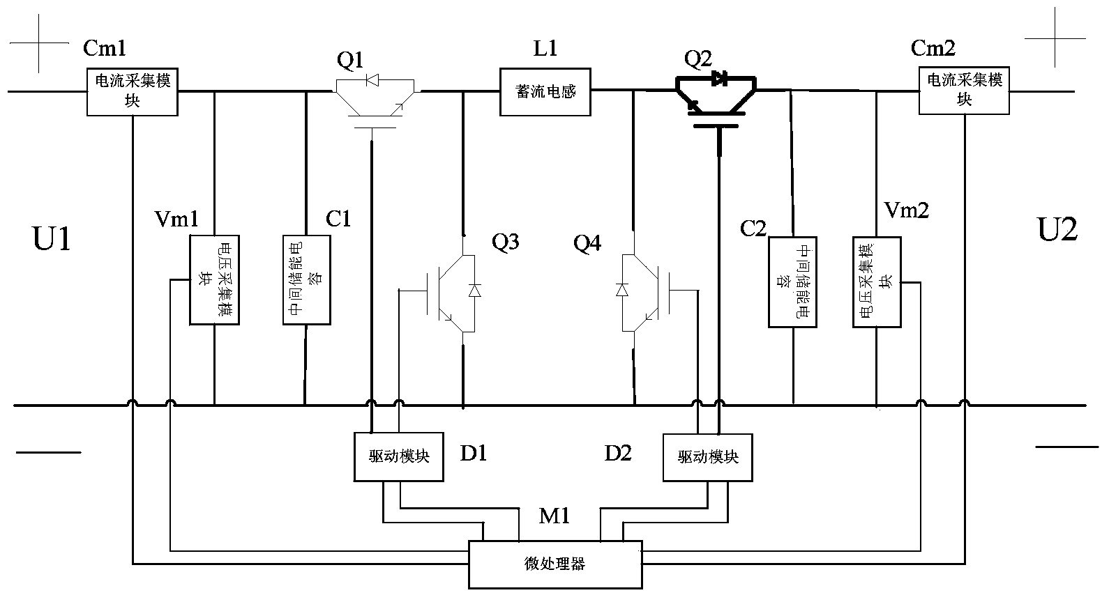
[0023] The bidirectional charging and discharging system with adjustable current and voltage of the present invention has U1 and U2 dual ports (such as figure 1 shown), consists of four IGBT modules (Q1, Q2, Q3, Q4) connected in parallel with diodes opposite to their conduction directions, two dual-unit IGBT drive modules (D1, D2), a current storage inductor (L1), It consists of two intermediate energy storage capacitors (C1, C2) at the input and output terminals, two voltage acquisition modules (Vm1, Vm2), two current acquisition modules (Cm1, Cm2) and a microprocessor (M1).
[0024] Between the positive terminal of U1 and the positive terminal of U2, there is a first current collection module Cm1 connected in series in sequence, the collector terminal is conn...
Embodiment 2
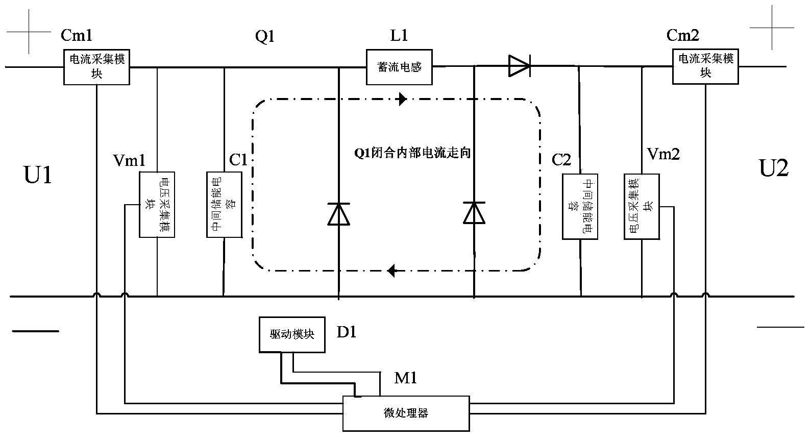
[0027] Taking supercapacitor charging as an example, U1 is used as the input terminal of the charging power supply, and U2 is used as the input terminal of the supercapacitor. When the U1 voltage is higher than the U2 voltage, the microprocessor M1 only controls the closing and opening of the pulse width modulation for Q1, and gives the opening signal control for Q2, Q3, and Q4. At this time, the IGBT modules Q2, Q3, Q4 acts like a diode. When Q1 is closed, the system circuit can be simplified as figure 2 In the circuit shown, the role of module Q1 is equivalent to that of a wire. At this time, the current storage inductor L1 in the circuit is in the energy storage stage, and the U1 terminal provides energy for the current storage inductor L1 and the intermediate energy storage capacitor C2, and then supplies power to the U2 terminal; when Q1 When disconnected, the whole circuit can be simplified as image 3In the circuit shown, the function of the module Q1 is equivalent t...
Embodiment 3
[0031] Taking the supercapacitor discharge as an example again, the U2 terminal is used as the supercapacitor access terminal, and the U1 terminal is used as the power output terminal. When the output terminal voltage requirement is lower than the supercapacitor voltage, the microprocessor M1 only conducts pulse width modulation control on Q2, and gives off signal control to Q1, Q3, and Q4. At this time, the IGBT modules Q1, Q3, and Q4 Acts like a diode. When Q2 is closed, the system circuit can be simplified as Image 6 In the circuit shown, the current storage inductor L1 in the circuit is in the energy storage stage at this time, and the U2 terminal provides energy for the current storage inductor L1 and the intermediate energy storage capacitor C1, and then supplies power to the U1 terminal; when Q2 is disconnected, the system circuit can be simplified For such Figure 7 In the circuit shown, at this time, the current storage inductor L1 in the circuit releases energy to...
PUM
 Abstract
Description
Claims
Application Information
 - R&D Engineer
- R&D Manager
- IP Professional
- Industry Leading Data Capabilities
- Powerful AI technology
- Patent DNA Extraction
Browse by: Latest US Patents, China's latest patents, Technical Efficacy Thesaurus, Application Domain, Technology Topic, Popular Technical Reports.
© 2024 PatSnap. All rights reserved.Legal|Privacy policy|Modern Slavery Act Transparency Statement|Sitemap|About US| Contact US: help@patsnap.com