
Insulation diagnostic method for high-voltage equipment in charged operating state

A high-voltage equipment, operating state technology, applied in the direction of testing dielectric strength, etc., can solve problems such as interference, decreased detection sensitivity, limited application, etc., to reduce the impact and reduce the difficulty of analysis.

Active Publication Date: 2014-07-16
GAUSS ELECTRONICS TECH
View PDF5 Cites 25 Cited by
  • Summary
  • Abstract
  • Description
  • Claims
  • Application Information

AI Technical Summary

Problems solved by technology

First, since the above-mentioned methods require relatively precise sensors to contact or be as close as possible to the high-voltage equipment in operation, it requires testers to be close to the high-voltage equipment, which may introduce personal safety issues; second, the above-mentioned traditional discharge signal-based measurement Or the detection method of temperature measurement is only used as a one-way signal receiving technology mode, which is more obviously affected by on-site interference. If the detection sensor is kept at a certain distance from the device body, the detection sensitivity will be significantly reduced, which limits the use of this type of technology in high-voltage operation. Application in Equipment Insulation Diagnosis

Method used


Image

  • Insulation diagnostic method for high-voltage equipment in charged operating state
  • Insulation diagnostic method for high-voltage equipment in charged operating state
  • Insulation diagnostic method for high-voltage equipment in charged operating state

Examples


Embodiment 1

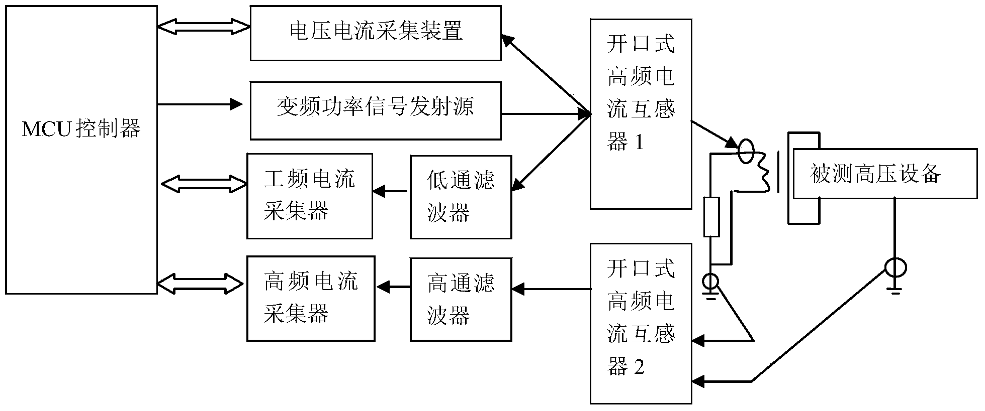
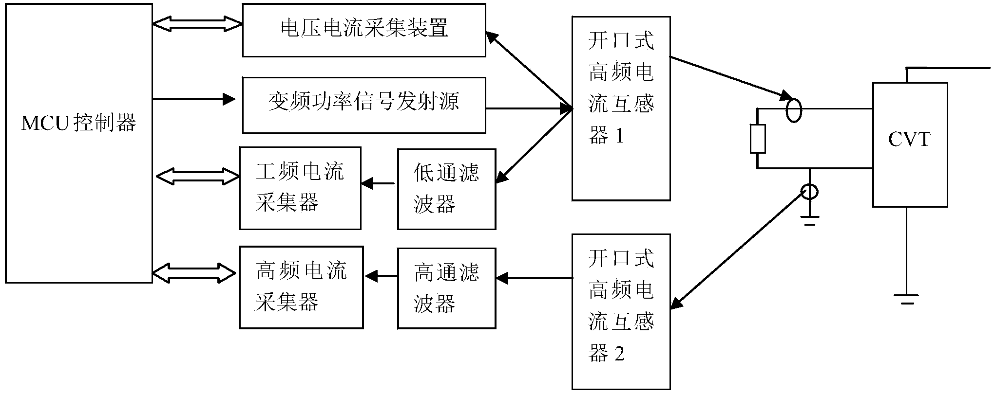
[0029] Such as figure 1 , image 3 shown. Insulation online diagnosis for 35kV independent CVT under electrified running state includes the following steps.

[0030] The first step is to build an insulation diagnosis system. Connect the secondary open end of the open-type high-frequency current transformer 1 to the cable of the secondary circuit of the CVT under test. The primary input end of the open-type high-frequency current transformer 1 is connected to the frequency conversion power signal controlled by the MCU controller. The output of the source is connected. The voltage and current collection device and the low-pass filter are respectively connected in parallel with the primary input end of the open-type high-frequency current transformer 1, and the output of the low-pass filter is connected with the power frequency current collector. The primary open end of the open-type high-frequency current transformer 2 is clamped to the grounding circuit of the secondary op...

Embodiment 2

[0051] Such as figure 1 , Figure 4 , Figure 5 As shown, the same place as that of Embodiment 1 will not be repeated, the difference is that the insulation on-line diagnosis is performed for the 10kV cable under the live running state. Connect the secondary open end of the open-type high-frequency current transformer 1 to the outer insulating protective sheath of the cable under test, and clamp the primary open end of the open-type high-frequency current transformer 2 to the grounding loop of the cable under test; The opening structures of the open-type high-frequency current transformer 1 and the open-type high-frequency current transformer 2 are rectangular. In order to play the role of on-site wiring indication, the open ends of the open-type high-frequency current transformer 1 and the open-type high-frequency current transformer 2 are provided with LED indicators.

[0052] Input the voltage amplitude of the output signal of the variable frequency power signal source ...


PUM


Abstract

The invention discloses an insulation diagnostic method for high-voltage equipment in a charged operating state. According to the method, by means of the electromagnetic induction principle, impact sweep frequency pulse signals output by a frequency conversion power signal source are coupled into the high-voltage equipment through a secondary loop of detected high-voltage equipment, then inductive coupling is carried out on leakage currents after the impact sweep frequency pulse signals are coupled into the detected high-voltage equipment through the loop, and equivalent earth impedance or dielectric loss factors of the high-voltage equipment operating with electricity are calculated by detecting release features of energy generated when the impact sweep frequency pulse signals are coupled and injected to an equivalent electrical loop of the high-voltage equipment, so that whether insulation breakdown discharge to the ground from the high-voltage equipment exists is analyzed. In comparison with the prior art, operating personnel do not need to be close to the primary high-voltage end of the equipment, synchronous transmitting and collecting are carried out by means of a frequency conversion test signal transmitting source and a corresponding receiver, the capacity of resisting disturbance is high, and the insulation state of the high-voltage equipment can be detected with high sensitivity on the condition of not cutting off the electricity.

Description

technical field [0001] The invention relates to a method for insulation diagnosis of high-voltage equipment in a live running state, in particular to an insulation diagnosis method for high-voltage equipment based on a coupling aliasing signal test in a non-power-off state. Background technique [0002] When the high-voltage equipment is in the running state, due to the power frequency withstand voltage, when the insulation has defects, a discharge signal may occur. Traditional methods for insulation diagnosis of high-voltage equipment in operation are mainly based on discharge signal measurement or temperature measurement, such as ultrasonic testing, high-frequency pulse current induction, and UHF testing. Insulation diagnosis of high-voltage equipment in operation, but there are the following defects in actual use. First, since the above-mentioned methods require relatively precise sensors to contact or be as close as possible to the operating high-voltage equipment body,...

Claims


Application Information

Patent Timeline
Patent Type & Authority Applications(China)
IPC IPC(8): G01R31/12
Inventor 张建张方荣
Owner GAUSS ELECTRONICS TECH
Learn More