
Pottery kiln cogeneration oil heat conduction device

A waste heat power generation and ceramic kiln technology, which is applied in the field of oil heat transfer devices, can solve problems such as low heat conversion efficiency, kiln damage, and product scrapping, and achieve the effects of high safety factor, convenient technical transformation, and large water saving

Inactive Publication Date: 2014-07-16
南志远
View PDF7 Cites 0 Cited by
  • Summary
  • Abstract
  • Description
  • Claims
  • Application Information

AI Technical Summary

Problems solved by technology

[0002] my country is a big country in the production of ceramics. The thermal energy devices provided are mainly heated by a single coal, gas, and oil. However, the current equipment that uses waste heat to generate power is to use the waste heat of traditional boilers to generate power, and its heat conversion efficiency is low. , the effect is slow, and the ceramic kiln itself is highly dependent on electricity. Normally, it is affected by electricity and natural factors. When a power outage occurs, a large number of products are scrapped, and even the kiln is damaged. Therefore, the waste heat generated by the ceramic kiln is fully utilized. , to produce cheap electricity for the enterprise's own use

Method used


Image

  • Pottery kiln cogeneration oil heat conduction device
  • Pottery kiln cogeneration oil heat conduction device
  • Pottery kiln cogeneration oil heat conduction device

Examples


Embodiment Construction

[0012] The present invention will be described in further detail below in conjunction with the accompanying drawings.

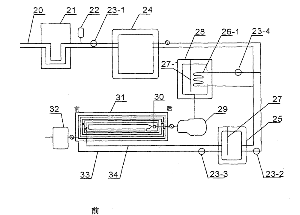
[0013] Such as figure 1 Shown, the present invention is connected with the pond (5) by the inlet of a feedwater pump (4), and the outlet passes through the feedwater pipeline (1) and a ceramic kiln (3) flue gas outlet and automatic heater (19) inlet Connect, connect the automatic heater (19) outlet with the steam-water separator (16) with the ascending pipeline (18), the descending pipeline (12) of the steam-water separator (16) and the pipeline pump (17), the pump outlet pipeline (1) One end is connected with the automatic feeder (19), the other end is connected with the automatic heater (13) on the upper end of the porcelain tube (2), the outlet of the automatic heater (13) is connected with the inlet of the steam-water separator (16) and the ascending pipe (15) , the upper end of the steam-water separator (16) is connected to the oil heat transfer device ...


PUM


Abstract

The invention relates to a pottery kiln cogeneration oil heat conduction device. The pottery kiln cogeneration oil heat conduction device comprises a water tank, a water feed pump, pottery kilns, a waste heat recovery system in each pottery kiln, a steam separator, a turbine and a generator, wherein the waste heat recovery system comprises two automatic heaters and an oil heat conduction device body, the automatic heaters are arranged at the position of a flue gas discharge port and at the upper end of a porcelain tube, and the oil heat conduction device body is arranged at the lower end of the porcelain tube. The pottery kiln cogeneration oil heat conduction device has the advantages of be capable of fully recycling waste heat of a pottery kiln roller way, achieving self-support of secondhand energy in enterprises, meanwhile, reducing production costs of the enterprises, and avoiding economic losses of the enterprises due to power failure influenced by factors such as power grid maintenance and natural weather; the oil heat conduction device is obvious in energy conservation, high in safety factor, environmental friendly, capable of achieving zero discharge, free of concentrated water and water scales, free from water softening, large in water saving amount, wide in use, long in service life, convenient to technically improve, and small in investment.

Description

technical field [0001] The invention relates to an oil heat conduction device for generating electricity with waste heat, in particular to an oil heat conduction device for generating electricity with waste heat of a ceramic kiln. Background technique [0002] my country is a big country in the production of ceramics. The thermal energy devices provided are mainly heated by a single coal, gas, and oil. However, the current equipment that uses waste heat to generate power is to use the waste heat of traditional boilers to generate power, and its heat conversion efficiency is low. , the effect is slow, and the ceramic kiln itself is highly dependent on electricity. Normally, it is affected by electricity and natural factors. When a power outage occurs, a large number of products are scrapped, and even the kiln is damaged. Therefore, the waste heat generated by the ceramic kiln is fully utilized. , to produce cheap electricity for the enterprise's own use. Realize the self-produ...

Claims


Application Information

Patent Timeline
Patent Type & Authority Applications(China)
IPC IPC(8): F27D17/00F22B1/18F22G1/00F01D15/10
CPCY02P10/25Y02P80/15
Inventor 南志远
Owner 南志远
Learn More