Light source module and backlight module

A light source module and backlight module technology, which is applied in the direction of light source, electric light source, slender light source, etc., can solve problems such as easy to produce deviation and affect the optical quality of the area, so as to improve the uniformity of light output, simplify the assembly process, and reduce optical darkness. zone effect

Inactive Publication Date: 2014-07-16
CORETRONIC (SUZHOU) CO LTD
View PDF6 Cites 1 Cited by
  • Summary
  • Abstract
  • Description
  • Claims
  • Application Information

AI Technical Summary

Problems solved by technology

However, according to the above assembly and positioning method, the connector 104 needs to be aligned when it is assembled into the backplane 106, but the alignment process is prone to deviation, and the area where the connector 104 is located cannot be provided with the light emitting diode 110, so it will be The backlight module 100 is displayed as an optically dark area, which affects the optical quality of this area

Method used


Image

  • Light source module and backlight module
  • Light source module and backlight module
  • Light source module and backlight module

Examples


Embodiment Construction

[0061] The aforementioned and other technical contents, features and effects of the present invention will be clearly presented in the following detailed description of the embodiments with reference to the drawings. The directional terms mentioned in the following embodiments, such as: up, down, left, right, front or back, etc., are only referring to the directions of the drawings. Accordingly, the directional terms are used to illustrate and not to limit the invention.

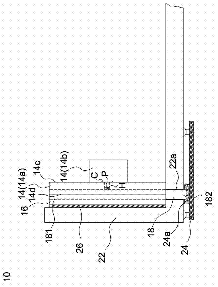
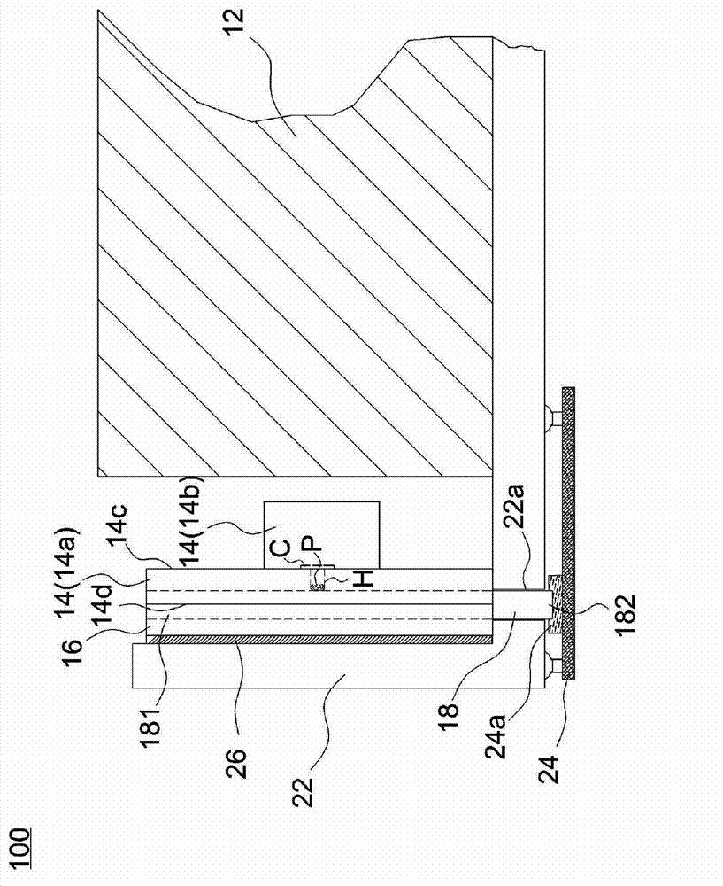
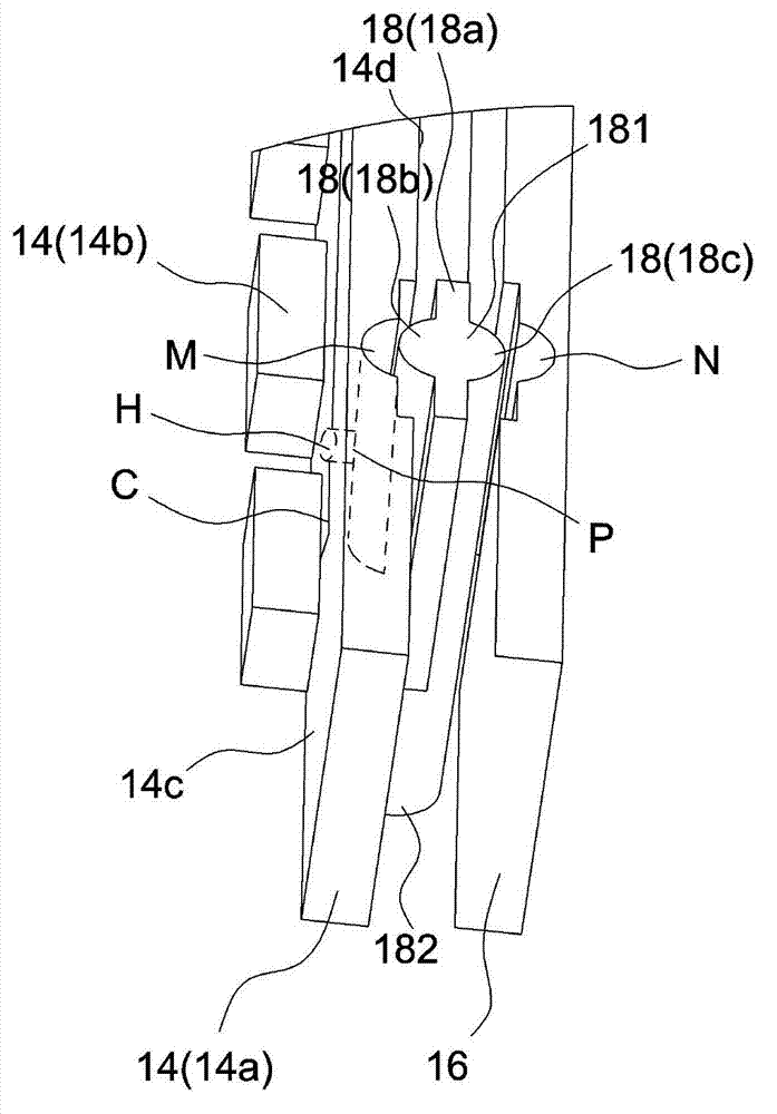
[0062] Figure 1A is a schematic diagram of a light source module according to an embodiment of the present invention, Figure 1B It is a schematic diagram of a backlight module according to an embodiment of the present invention. Please refer to Figure 1A and Figure 1B , a light source module 10 includes an LED strip 14 , a heat sink 16 , a conductive block 18 and a power circuit board 24 . exist Figure 1BAmong them, a backlight module 100 includes a light guide plate 12 and a light source module 1...


PUM


Abstract

The invention discloses a light source module and a backlight module. The light source module comprises a light emitting diode (LED) lamp strip, an electric conduction block and a power source circuit board, wherein the LED lamp strip comprises a base board and at least an LED, at least an electric conduction connection pad and a circuit pattern are formed on the base board, the circuit pattern is connected with the electric conduction connection pad and the LED, the electric conduction block is arranged on the base board of the LED lamp strip and provided with a first end and a second end, the first end of the electric conduction block is electrically connected with the electric conduction connection pad, and the second end of the electric conduction block is electrically connected with the power source circuit board.

Description

technical field [0001] The invention relates to a light source module, and in particular to a connection method of the light source module. Background technique [0002] Figure 5 It is a schematic diagram of a known backlight module. like Figure 5 As shown, in the backlight module 100, a plurality of LEDs 110 are arranged on the LED light bar 102, the connector 104 of the LED light bar 102 is positioned in the positioning groove 108 of the backplane 106, and the LED light bar 102 uses A thermally conductive tape (not shown) is pasted on the side of the backplane 106 to be fixed on the backplane 106 . However, according to the above assembly and positioning method, the connector 104 needs to be aligned when it is assembled into the backplane 106, but the alignment process is prone to deviation, and the area where the connector 104 is located cannot be provided with the light emitting diode 110, so it will be The display on the backlight module 100 is an optically dark are...

Claims


Application Information

Patent Timeline
Patent Type & Authority Applications(China)
IPC IPC(8): F21S8/00F21V23/06F21Y101/02F21Y103/10F21Y115/10
Inventor 李弦
Owner CORETRONIC (SUZHOU) CO LTD
Why Eureka
Try Eureka