Quick tower split raft foundation

A technology of split raft and raft foundation, which can be used in infrastructure engineering, construction, etc., and can solve the problems of quality, difficult to guarantee construction period, large amount of concrete pouring and ramming, and long construction period.

Active Publication Date: 2014-07-16
SHANDONG ZHONGNENG TOWER
View PDF6 Cites 2 Cited by
  • Summary
  • Abstract
  • Description
  • Claims
  • Application Information

AI Technical Summary

Problems solved by technology

In the case of poor foundation geological conditions, the raft foundation is mainly used as the foundation of the tower. Although it is a common method for the foundation construction geological conditions of the tower at the present stage, the construction period is extremely long, and the amount of concrete poured on site is very large. Traditional cast-in-place For raft foundations, after the excavation of the foundation pit, formwork needs to be assembled, steel bars are welded and bound on site, and concrete is also prepared on site in remote areas, which requires auxiliary equipment such as mixers, power supplies, vibrators, and transportation tools. The quality of concrete poured on site is affected by the climate. , the environment, the technical level of construction personnel, etc., it is difficult to achieve the designed concrete strength
There was a construction team who made C30 concrete into C10 strength, and the quality was difficult to control, especially in winter construction, the quality and construction period were more difficult to guarantee, and the cycle was long, which brought a large social workload
The cast-in-place concrete raft foundation can only be used once and cannot be reused
Due to the wet operation produced by mixing concrete on site, it polluted the surrounding environment

Method used


Image

  • Quick tower split raft foundation
  • Quick tower split raft foundation
  • Quick tower split raft foundation

Examples


Embodiment Construction

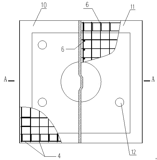
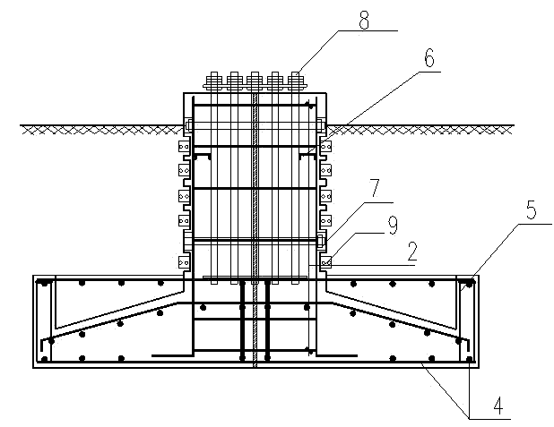
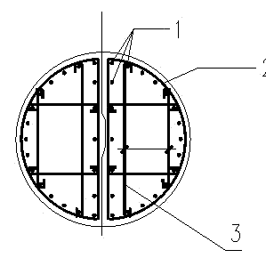
[0015] The present invention will be described in further detail below in conjunction with the accompanying drawings and specific embodiments. It can be seen from the accompanying drawings that a pole-tower split raft foundation quick-installation foundation of this program includes a raft foundation, and is characterized in that: the raft foundation is made of raft The raft foundation I10 and the raft foundation II11 are composed of a concrete rectangular base and a concrete semi-column integrated at the upper end respectively, and steel bars are set in the raft foundation I10 and the raft foundation II11. Anchor bolts 8 are arranged in the concrete half cylinder, and hoops 9 are arranged on the surface of the concrete half cylinder. The concrete semi-cylindrical contact surfaces of the raft foundation I10 and the raft foundation II11 are engaged. The steel bars in the concrete semi-cylinder are composed of vertical main bars 1, spiral bars 2 spirally wound around the main ba...


PUM


Abstract

The invention discloses a quick tower split raft foundation comprising a raft foundation body. The quick tower split raft foundation is characterized in that the raft foundation body includes a raft foundation body I and a raft foundation body II which respectively comprise concrete rectangular bases and concrete half cylinders integrally located at one upper ends of the concrete rectangular bases, steel bars are arranged in the raft foundation body I and the raft foundation body II, anchor bolts are arranged in the concrete half cylinders, and hoops are arranged on the surface of the concrete half cylinders. The quick tower split raft foundation has the advantages that the quick tower split raft foundation is a precast product, is processed and formed through a factorial standard die, is maintained through steam, is high in strength and has high generality, and processing quality can be guaranteed; 2, on-site construction is quick, pit digging and pole assembling can be completed in one day; a tower to be transferred and a mobile base station can be hung and transported for a second time, reusing is implemented, and cost is reduced.

Description

technical field [0001] The invention belongs to the technical field of electric power communication transmission equipment, and in particular relates to a pole-tower split raft foundation quick-installation foundation. Background technique [0002] With the rapid development of the national economy and the continuous development of modern electric power and communication technology, it is necessary to build a large number of transmission lines and mobile communication base stations to meet the requirements. Therefore, towers with different strengths, bending moments, and lengths are widely used, and the foundation construction of towers is very critical. According to the geological conditions of the line and base station pole positions, the existing foundation methods of transmission line towers and mobile communication towers are as follows: steel pipe pile foundation, cast-in-place pile foundation, and raft foundation. Among the three foundations, only the raft foundation...

Claims


Application Information

Patent Timeline
Patent Type & Authority Applications(China)
IPC IPC(8): E02D27/42E02D27/01
Inventor 郭志涛
Owner SHANDONG ZHONGNENG TOWER
Why Eureka
Try Eureka