A submersible aerator with grinding device

A technology for aerators and submersible motors, applied in water aeration, water/sludge/sewage treatment, sustainable biological treatment, etc., can solve problems such as water inlet clogging, and achieve the effect of improving clogging problems

Active Publication Date: 2016-04-06
JIANGSU UNIV
View PDF4 Cites 0 Cited by
  • Summary
  • Abstract
  • Description
  • Claims
  • Application Information

AI Technical Summary

Problems solved by technology

[0003] The purpose of the present invention is to solve the problem of clogging of the water inlet of the common submersible aerator, and to provide a submersible aerator with a grinding device. The problem has been improved to a certain extent, and the aeration efficiency of the aerator can be improved

Method used


Image

  • A submersible aerator with grinding device
  • A submersible aerator with grinding device
  • A submersible aerator with grinding device

Examples


Embodiment Construction

[0016] The present invention will be further described below in conjunction with the accompanying drawings and specific embodiments, but the protection scope of the present invention is not limited thereto.

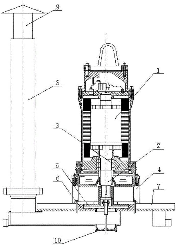
[0017] figure 1 Shown is a schematic structural view of the aerator with a crushing and grinding device according to the present invention. The aerator includes a submersible motor 1 , a hollow drive shaft 2 , an elastic coupling 3 , a body 4 , an impeller 5 , a mixing chamber 6 , a mixing vane 7 , an injection pipe 8 , and an air intake pipe 9 . A grinding device 10 is arranged at the water inlet of the aerator. The submersible motor 1 is connected to the hollow drive shaft 2 through an elastic coupling 3; the impeller 5 is installed on the other end of the hollow drive shaft 2, and the shaft end of the impeller 5 is connected to the shaft of the grinding device 10 through the elastic coupling 3, The grinding device 10 is installed at the shaft end water inlet of the h...


PUM


Abstract

The invention provides a submerged aerator with a rubbing device, wherein the rubbing device is installed at the water inlet of the aerator, a submersible motor is connected with a hollow driving shaft through an elastic coupler, an impeller is installed at the other end of the hollow driving shaft, the shaft end of the impeller is connected with the shaft of the rubbing device through the elastic coupler, and the rubbing device is installed at the water inlet at the shaft end of the hollow driving shaft. Under the rotating effect of the rubbing device, garbage entering into the water inlet is rubbed quickly under quick rotation of a rubbing knife, so that the plugging problem of the water inlet is greatly improved, and the aerating efficiency of the aerator is expanded.

Description

technical field [0001] The invention relates to a submersible aerator, in particular to a submersible aerator with a grinding device. Background technique [0002] Aeration is a very important process in sewage biochemical treatment. The submersible aerator is driven by a submersible motor to rotate the impeller at high speed, and the impeller generates strong centrifugal force. Under the action of centrifugal force, a negative pressure zone is formed around the impeller, thereby generating self-suction A large amount of fresh air in the atmosphere is continuously inhaled through the suction pipe, and at the same time, the impeller sucks the sewage into the suction hood. In the suction hood, the sewage and the inhaled air collide with each other to form a large number of ultra-fine bubbles and spray them around through the diversion groove. , the jetted gas-liquid mixed flow produces the effect of agitation and convection. However, the current aerator often has the problem ...

Claims


Application Information

Patent Timeline
Patent Type & Authority Patents(China)
IPC IPC(8): C02F3/02C02F7/00
CPCY02W10/10
Inventor 张帆付强王洪亮王秀礼王鹏
Owner JIANGSU UNIV
Why Eureka
Try Eureka