
A lower exhaust cyclone separator

A cyclone separator and exhaust pipe technology, which is applied to swirl devices, devices whose axial directions of swirl can be reversed, etc. The effect of reducing blow-by gas, improving removal effect, and high removal efficiency

Inactive Publication Date: 2016-03-09
HARBIN INST OF TECH AT WEIHAI
View PDF13 Cites 0 Cited by
  • Summary
  • Abstract
  • Description
  • Claims
  • Application Information

AI Technical Summary

Problems solved by technology

A relatively simple agglomeration method is to agglomerate fine particles by increasing turbulence, such as the US patent "Methodandapparatusformixingfluidsforparticleagglomeration" (US20060256649A1), which uses vertically arranged blades to mix the airflows flowing in different channels, and enhances turbulence to agglomerate fine particles, but the blade shape The complex and long-term use of the sheet structure is not wear-resistant and easy to break; the Chinese patent "gas-solid jet-acoustic field ultrafine particle coupling packaging and agglomeration device" (CN101091860B), through the introduction of external jets to enhance the disturbance to make the fine particles agglomerate, but this method Additional jet pipelines are required, the application is more complicated, and additional investment costs are required

Method used


Image

  • A lower exhaust cyclone separator
  • A lower exhaust cyclone separator
  • A lower exhaust cyclone separator

Examples


Embodiment Construction

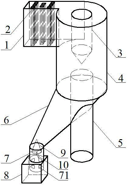
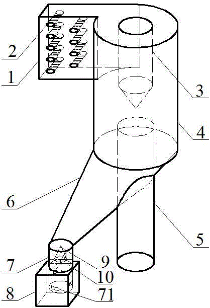
[0019] from figure 1 , figure 2 As can be seen in the figure, a lower exhaust cyclone separator includes an air intake pipe 1, a guide body 3, a cylinder body 4, an exhaust pipe 5, an ash hopper 6, an ash discharge pipe 7 and an ash bin 8. The guide body 3 is located in the cylinder body 4, the exhaust pipe 5 is located below the guide body 3, the ash hopper 6 is arranged obliquely downward, the upper part is connected with the cylinder body 4, and the lower part is connected with the ash discharge pipe 7, the ash discharge hopper Pipe 7 lower part stretches in the ash bin 8.

[0020] The feature of the present invention is that: several bypass columns 2 are installed in the air inlet pipe 1 . The surface of the circumventing column 2 is provided with several grooves 21 along the direction of air flow, and several through holes 22 are arranged in the middle along the direction of air flow, and several circumventing columns 2 are horizontally or vertically staggered in the a...


PUM


Abstract

The invention relates to a down-exhaust cyclone separator. The down-exhaust cyclone separator comprises an air inlet pipe, a cylinder, a flow guide body, an exhaust pipe, an ash dropping hopper, an ash discharge pipe and an ash bin, wherein the flow guide body is located in the cylinder, the exhaust pipe is located under the flow guide body, the ash dropping hopper is arranged slantwise downwards, the upper part of the ash dropping hopper is connected to the cylinder while the lower part of the ash dropping hopper is connected to the ash discharge pipe, the lower part of the ash discharge pipe extends into the ash bin, a plurality of flow-around columns are mounted in the air inlet pipe, a cone is mounted in the ash discharge pipe by use of a support frame, the peak of the cone is at top while the bottom surface of the cone is at bottom, a plurality of ash discharge openings are formed in the wall of the ash discharge pipe in the ash bin, a plurality of grooves are formed in the surfaces of the flow-around columns in an air flowing direction, a plurality of through holes are formed between the grooves, and the plurality of flow-around columns are arranged horizontally or vertically in a staggered way in the air flowing direction in the air inlet pipe. The down-exhaust cyclone separator is reasonable in structure, simple in structure and high in separation efficiency. Especially, the down-exhaust cyclone separator has high fine particle removal efficiency, and therefore, discharged fine particles can be effectively reduced.

Description

Technical field [0001] The invention belongs to the field of flue gas dust removal and gas-solid separation, and is specifically a lower exhaust cyclone separator. Background technique [0002] The commonly used cyclone separator is of the upper exhaust type, which usually consists of an air inlet pipe, a cylinder, a cone, an exhaust pipe, an ash discharge pipe and an ash bin. The airflow of this cyclone separator first flows upward along the flue and into the cylinder through the air inlet pipe, then flows out of the exhaust pipe, and finally enters the flue downward again. Multiple turns of the air flow during this process will produce a large pressure loss, and this pressure loss does not play a positive role in the separation process. Moreover, it is also difficult to arrange and support the upper exhaust cyclone separator with the exhaust pipe pointing upward. [0003] An improvement to the upper exhaust cyclone separator is to add a reverse cone or small cylinder ins...

Claims


Application Information

Patent Timeline
Patent Type & Authority Patents(China)
IPC IPC(8): B04C5/00B04C5/04B04C5/185
Inventor 郝晓文杨建国张志军
Owner HARBIN INST OF TECH AT WEIHAI
Learn More