Optical detection method for polar axis type telescope polar axis shaking errors

An optical detection and telescope technology, which is used in optical instrument testing, machine/structural component testing, and measuring devices, etc., can solve problems such as complex calculation processes, achieve high measurement accuracy, avoid mathematical calculation processes, and simple principles.

Active Publication Date: 2014-07-09
CHANGCHUN INST OF OPTICS FINE MECHANICS & PHYSICS CHINESE ACAD OF SCI
View PDF8 Cites 2 Cited by
  • Summary
  • Abstract
  • Description
  • Claims
  • Application Information

AI Technical Summary

Problems solved by technology

[0011] In order to solve the problem that the existing star calibration method is used to detect the polar axis shaking error of the polar axis telescope, the calculation process is complicated, and the distribution positi...

Method used


Image

  • Optical detection method for polar axis type telescope polar axis shaking errors
  • Optical detection method for polar axis type telescope polar axis shaking errors
  • Optical detection method for polar axis type telescope polar axis shaking errors

Examples


Embodiment Construction

[0023] The present invention will be described in further detail below in conjunction with the accompanying drawings.

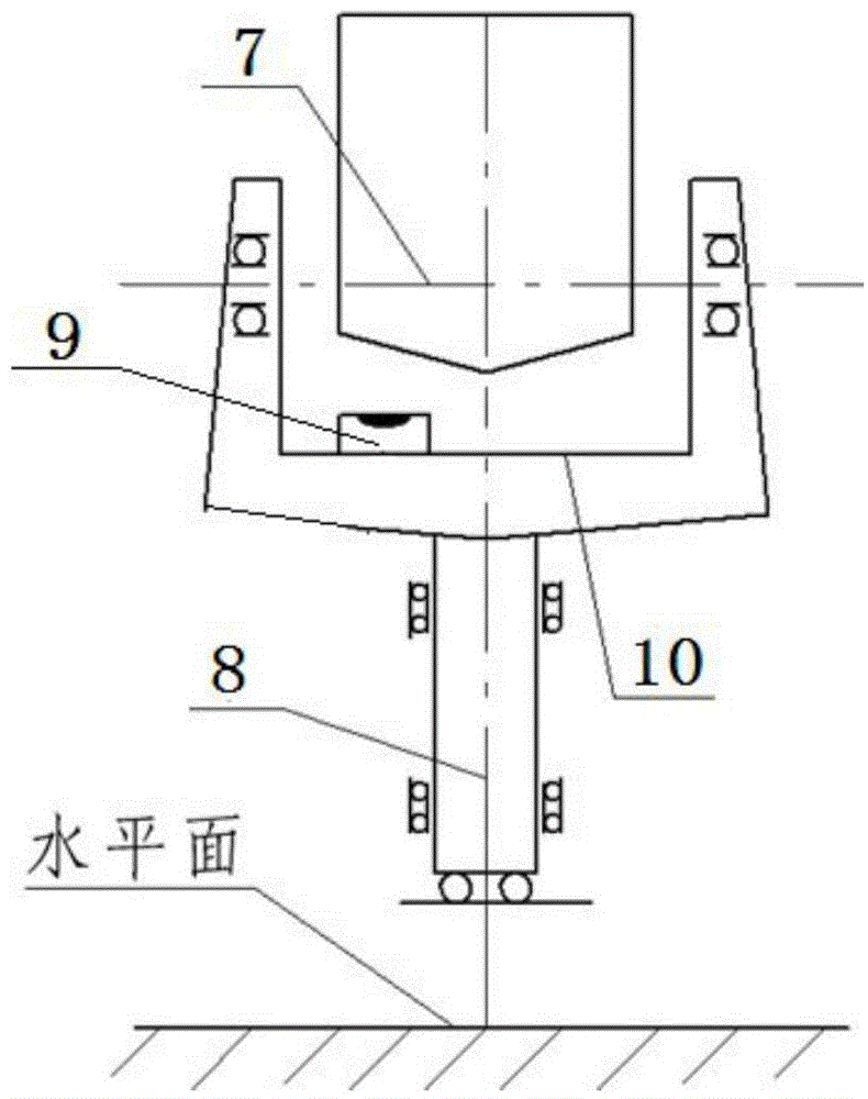
[0024] Such as figure 2 As shown, the optical detection method of the polar axis shake error of the polar axis type telescope of the present invention comprises the following steps:

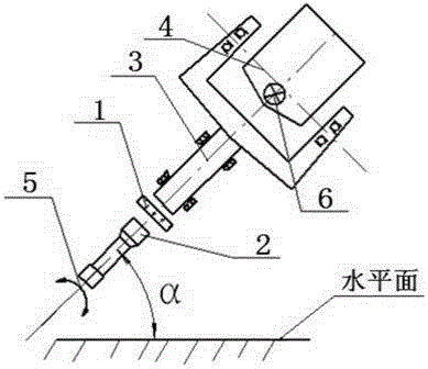
[0025] (1) Install a plane reflector 1 with two degrees of freedom adjustment mechanism on the shaft head of the polar axis 3 of the polar axis telescope, and use a 0.2" collimator 2 placed obliquely to align the plane reflector 1. The optical axis of the 0.2" collimator 2 is parallel to the axis of the polar axis 3.

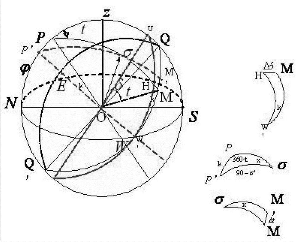
[0026] (2) Rotate the polar axis 3 at intervals of 30°, and at the same time read the component data in the pitch direction 5 and the component data in the azimuth direction 6 on the 0.2" collimator 2, and rotate 360° continuously, measuring 12 in total point, the above process is repeated 4 times, and the data read on the 0.2"collimator 2 are recorded in the e...


PUM


Abstract

The invention relates to the field of telescope axis detection, in particular to an optical detection method for polar axis type telescope polar axis shaking errors. The problems that when a star calibration method is used for detecting the polar axis shaking errors of a polar axis type telescope, the calculating process is complex, the position of a fixed star needs to be known in advance, and the method is limited by weather and places are solved. The method comprises the steps that a plane mirror is arranged on an axis head of a polar axis, meanwhile, an obliquely-arranged 0.2'' parallel collimator is adopted to be aligned to the plane mirror, and the optical axis of the 0.2'' parallel collimator is parallel to the axis of the polar axis; the polar axis is rotated once every a certain angle, meanwhile, component data in the pitching direction and the orientation direction are respectively read on the 0.2'' parallel collimator, the polar axis is continuously rotated by 360 degrees, and the process is repeated four times; data processing is carried out through a Fourier hamonic function, and the root-mean-square value of the axis of the polar axis on pitching and orientation shaking components is calculated based on the Bessel formula. According to the method, the position of the fixed star does not need to be known, the method is not limited by the weather and the places, no complex mathematical calculation process exists, implementation is easy, convenience and reliability are achieved, and measuring precision is high.

Description

technical field [0001] The invention relates to the technical field of telescope axis detection, in particular to an optical detection method for polar axis shaking errors of a polar axis telescope. Background technique [0002] Such as figure 1 As shown, the ground-level frame structure is a structural form of the telescope. It has two mutually perpendicular rotation axes, one is located in the horizontal plane, called the horizontal axis 7, and the other is perpendicular to the horizontal plane, called the vertical axis 8. Due to processing errors and assembly errors, the vertical shaft system produces shaking during operation, which will have a certain impact on pointing accuracy. At present, the measurement method of the electronic level 9 is used to measure the shaking error of the vertical shaft system, that is, the electronic level 9 is placed on the plane of the vertical axis turntable 10, and by recording the reading values ​​of the electronic level 9 when the vert...

Claims


Application Information

Patent Timeline
IPC IPC(8): G01M11/08
Inventor 王志王建立周超曹玉岩王志臣
Owner CHANGCHUN INST OF OPTICS FINE MECHANICS & PHYSICS CHINESE ACAD OF SCI
Why Eureka
Try Eureka