
Exhaust gas recirculation device for vehicle engine

A technology of exhaust gas recirculation and engine, which is applied in the direction of engine components, machines/engines, exhaust gas recirculation, etc., and can solve the problems of exhaust gas sensor immersion cracking performance, degradation, etc.

Inactive Publication Date: 2016-09-07
SUZUKI MOTOR CORP
View PDF6 Cites 0 Cited by
  • Summary
  • Abstract
  • Description
  • Claims
  • Application Information

AI Technical Summary

Problems solved by technology

Then, the condensed water introduced into the exhaust port flows to the exhaust manifold due to the flow velocity of the exhaust gas, and further flows to the exhaust gas sensor installed in the exhaust manifold. If the exhaust gas sensor contacts the condensed water, the exhaust gas sensor may be soaked in water, cracked or its performance will be reduced.

Method used


Image

  • Exhaust gas recirculation device for vehicle engine
  • Exhaust gas recirculation device for vehicle engine
  • Exhaust gas recirculation device for vehicle engine

Examples


Embodiment Construction

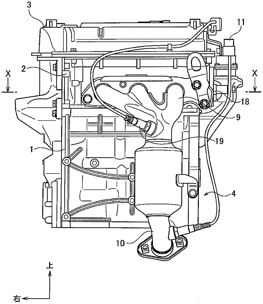
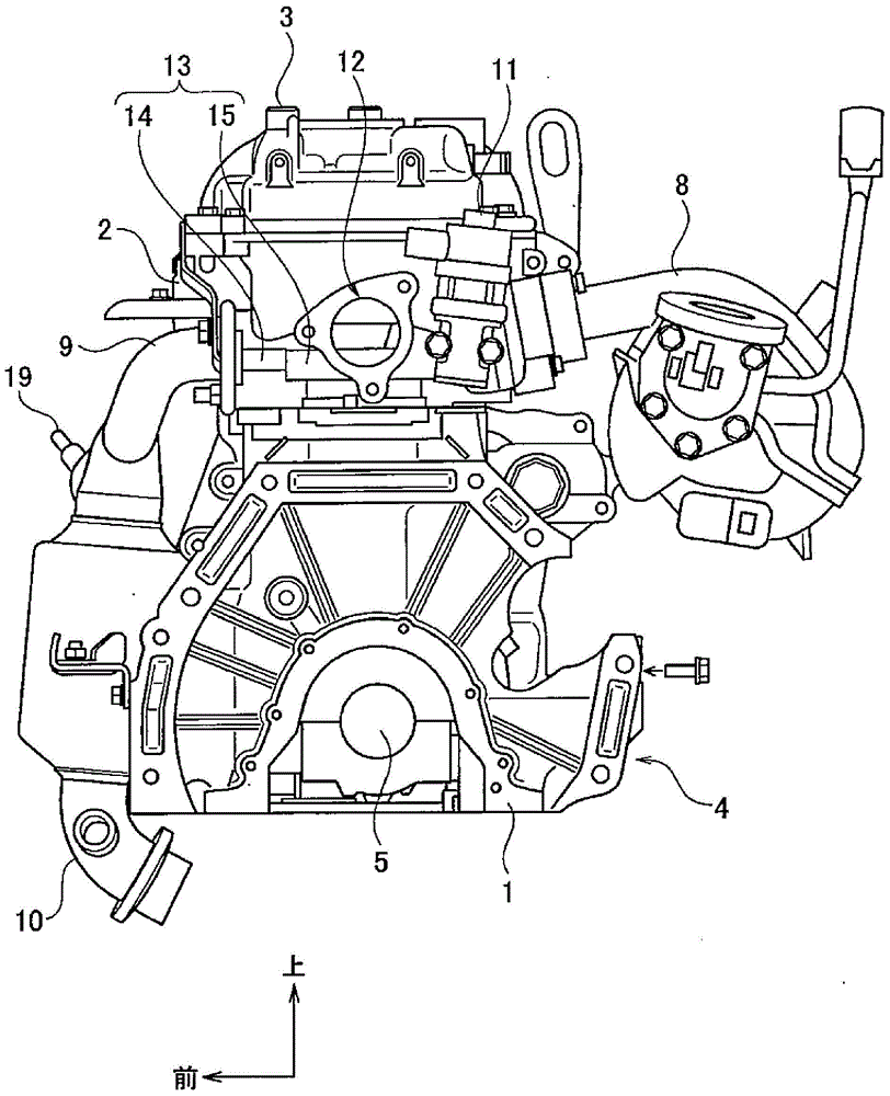
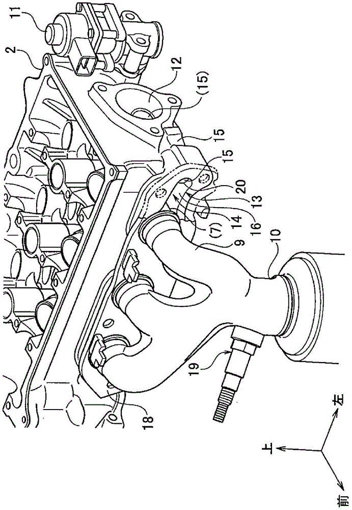
[0028] Next, a first embodiment of an exhaust gas recirculation device for a vehicle engine according to the present invention will be described with reference to the drawings. figure 1 It is a front view of the vehicle engine of this embodiment, figure 2 yes figure 1 side view of a vehicle with engine. In the vehicle engine of the present embodiment, a cylinder head 2 is attached to the upper end surface of the cylinder block 1 , and a cylinder head cover 3 is attached to the upper end surface of the cylinder head 2 . A crankcase 4 is formed at a lower portion of the cylinder block 1, and a crankshaft 5 is housed in the crankcase 4 so as to be rotatable. In addition, an oil pan (not shown) is mounted on the lower end surface of the cylinder block 1 . In this vehicle engine, the figure 1 The right side of the diagram is equipped with a transmission not shown.

[0029] On the joint surface of the cylinder head 2 and the cylinder block 1 , a plurality of, in this embodiment,...


PUM


Abstract

The device has a downstream passage portion (14, 15) formed as a part of an exhaust gas recirculation passage (13) and intersected with cylinder banks. The downstream passage portion is connected to an upstream passage portion and cooled by cooling water in a cooling water passage. A projecting wall is formed on a side of the exhaust gas recirculation passage of an upstream end portion of an outlet section. The projecting wall is protruded from a floor surface along a direction of an upper surface. The protruding wall is formed with a preset space with respect to the upper surface.

Description

technical field [0001] The present invention relates to an exhaust gas recirculation device for a vehicle engine used in a vehicle, and is suitable for forming an exhaust gas recirculation passage in a cylinder head for returning a part of exhaust gas flowing through an exhaust port to an intake port or an intake manifold . Background technique [0002] As an exhaust gas recirculation device for a vehicle engine in which the exhaust gas recirculation passage is formed in the cylinder head, there is, for example, the device described in Japanese Patent Laid-Open No. 2011-43096. In the exhaust gas recirculation device of the vehicle engine, a groove continuous with the exhaust port is formed in the direction of the cylinder row, that is, the direction of the crankshaft, on one side of the cylinder head on which the exhaust manifold is mounted. A portion of the groove opposite to the exhaust port is connected to a downstream portion of an exhaust gas recirculation passage form...

Claims


Application Information

Patent Timeline
Patent Type & Authority Patents(China)
IPC IPC(8): F02M26/14F02M26/15
Inventor 石原康臣
Owner SUZUKI MOTOR CORP
Learn More