Eureka AIR delivers breakthrough ideas for toughest innovation challenges, trusted by R&D personnel around the world.

Bi-directional spiral material-discharging bin

A two-way spiral, discharge bin technology, applied in the directions of transportation and packaging, loading/unloading, etc., can solve the problems of high maintenance and operation cost, complex structure, large discharge impact, etc., to achieve low maintenance and operation cost, blanking The effect of uniform distribution and small discharge impact

Inactive Publication Date: 2014-07-09
杨晓初
View PDF5 Cites 7 Cited by
  • Summary
  • Abstract
  • Description
  • Claims
  • Application Information

AI Technical Summary

Problems solved by technology

[0004] (1) The structure is complex and bulky, which directly leads to a substantial increase in its own weight and manufacturing cost
[0005] (2) The alternate frequent opening and closing of the upper and lower discharge valves and the alternate frequent intake and exhaust of the intake and exhaust systems greatly reduce the service life of the seals and friction pairs in the upper and lower discharge valves, increase energy consumption and generate
[0006] Loud exhaust noise, resulting in poor reliability, high maintenance and operating costs
[0007] (3) Intermittent discharge and each discharge volume is large, resulting in a large discharge impact and uneven distribution of the discharge, causing greater difficulties for subsequent material transportation

Method used


Image

  • Bi-directional spiral material-discharging bin
  • Bi-directional spiral material-discharging bin

Examples


Embodiment Construction

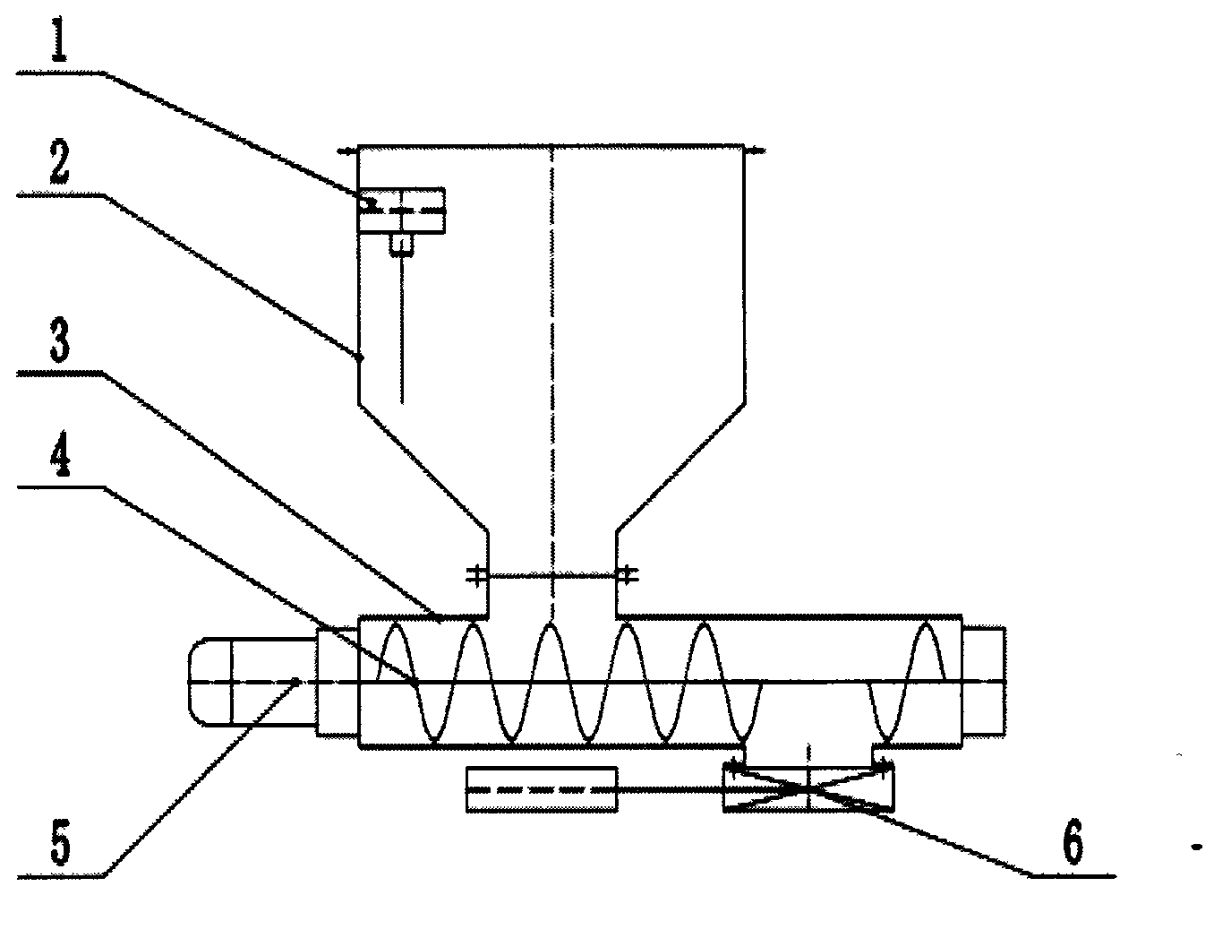
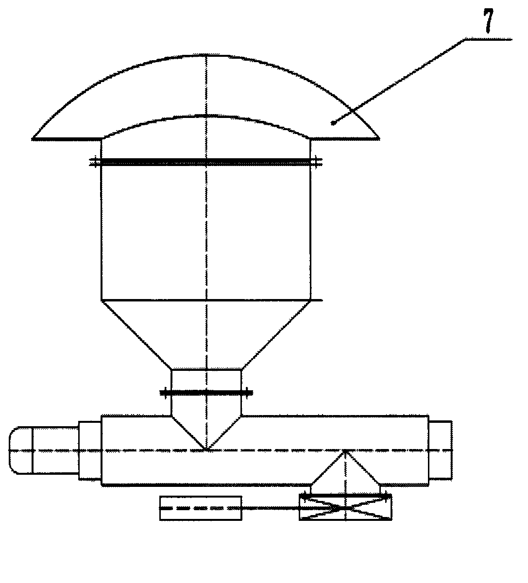
[0015] exist figure 1 Among them, the present invention includes a level meter 1, a discharge bin body 2, a push bin 3, a motor transmission device 4, a two-way screw 5 and a discharge valve 6, wherein the upper part of the discharge bin body 2 is cylindrical and the bottom is conical shape, and there is a material outlet at the bottom of the cone, the pusher bin 3 is cylindrical, with an upper feed port and a lower discharge port, the two-way screw 5 pusher bin 3 is a forward spiral, the pusher bin 3. The tail end is a reverse spiral. The level meter 1 for measuring the height of the accumulated material in the discharge bin body 2 is fixedly installed inside the discharge bin body 2. The outlet flange of the bottom material is sealed and connected by bolts, and the discharge valve 6 is sealed and connected with the flange of the lower discharge port of the push bin 3 by bolts.

[0016] exist figure 2 Among them, the upper flange of the discharge bin body 2 is sealed and c...


PUM


Abstract

A bi-directional spiral material-discharging bin is composed of a material level instrument, a material-discharging bin body, a material-pushing bin, a motor transmission device, a screw and a blow-off valve. The upper portion of the material-discharging bin body is cylindrical, the bottom of the material-discharging bin body is conical, a cone base is provided with a material outlet, the material-pushing bin is cylindrical and is provided with an upper feed port and a lower discharging port, the material-pushing bin end of the bi-directional screw is spiral in the forward direction, the tail end of the material-pushing bin is spiral in the reverse direction, the material level instrument for measuring the height of an accumulated material in the material-discharging bin body is fixedly installed in the material-discharging bin body, an upper feeding port flange on the material-pushing bin is in sealed connection with a cone base material outlet flange of the material-discharging bin body in a bolted connection mode, and the blow-off valve is in sealed connection with a material-pushing bin lower discharging port flange in a bolted connection mode. The problem that due to the inborn inherent defects of a traditional material-discharging bin in structural design, the traditional material-discharging bin is complex in structure and large in volume is large, easily-damaged parts are many, the reliability is poor, the traditional material-discharging bin does not save energy and is not environmentally friendly, intermittent discharge is caused, and large discharging impact is caused is solved well.

Description

technical field [0001] The invention relates to a discharge device which can not only keep the reliable seal of the airtight container, but also continuously discharge the solid-phase fine particle material in the airtight container, especially refers to the two-way pressurized filter for filtering the suspension Spiral discharge bin. Background technique [0002] At present, the traditional discharge bin of the pressurized filter is composed of an upper discharge bin body, an upper discharge valve, a lower discharge bin body, a lower discharge valve, a level meter and a supporting system, which are sequentially sealed and connected. Including intake and exhaust system, hydraulic system and electrical control system. The disc filter in the pressurized filter is installed in a closed pressurized cabin, and the solid-phase fine particle materials filtered out by the disc filter are first conveyed to the upper discharge that is sealed and connected with the discharge port of t...

Claims


Application Information

Patent Timeline
IPC IPC(8): B65G65/46
Inventor 杨晓初
Owner 杨晓初
Why Eureka
Eureka Blog
Learn More