
Reverse drawing method for soft die with peripheral auxiliary thrust

An auxiliary thrust and reverse drawing technology, applied in forming tools, manufacturing tools, metal processing equipment, etc., can solve the problems of increasing the friction between the plate and the die, increasing the drawing force, and being unfavorable for forming, and achieves the improvement of forming limit, Ease of sealing, lower cost and energy consumption

Inactive Publication Date: 2014-07-09
YANSHAN UNIV
View PDF9 Cites 10 Cited by
  • Summary
  • Abstract
  • Description
  • Claims
  • Application Information

AI Technical Summary

Problems solved by technology

In this patent, after the radial granular medium is pushed by the top plate, it is easy to plug into the gap between the sheet material, the die and the positioner, which increases the friction between the sheet material and the mold, increases the drawing force, and is not conducive to forming; at the same time, the granular medium is in the There is an attenuation effect in the process of force transmission, and the thickness of the sheet metal in the reverse drawing process is relatively thin, and the thrust exerted by the granular medium on the end face of the sheet metal is very limited

Method used


Image

  • Reverse drawing method for soft die with peripheral auxiliary thrust
  • Reverse drawing method for soft die with peripheral auxiliary thrust

Examples


Embodiment 1

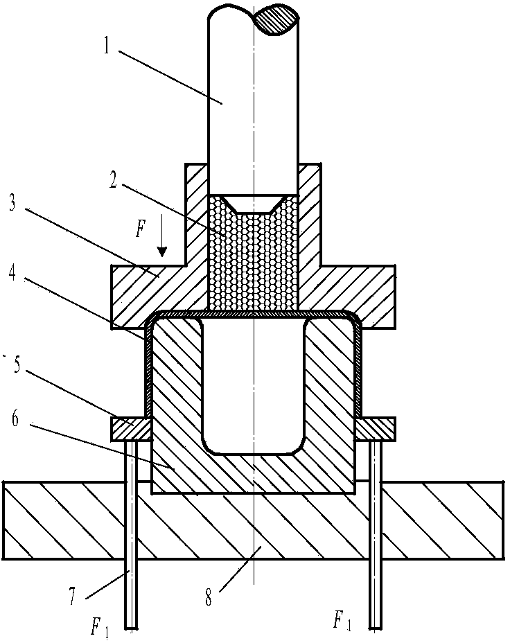
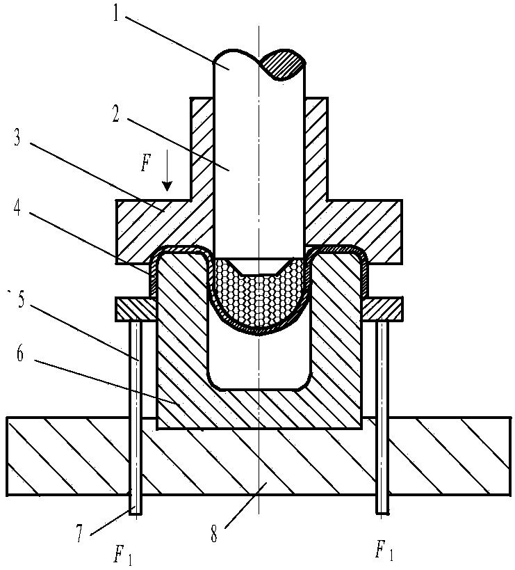
[0017] Fasten the pre-formed 304 stainless steel plate cylindrical part on the die, place the blank holder on the bottom of the cylindrical part and apply a blank holder force F. The granular medium in the barrel is 0.2~0.3mm in diameter Stainless steel ball, the charging height is 1.5 times the diameter of the punch, the punch compresses the medium downward, and applies pressure to the cylindrical part to form a soft punch; at the same time, the 4 ejector rods evenly distributed under the thrust ring are cylindrical The end of the piece provides a circumferential auxiliary thrust F 1 , The force is provided by the hydraulic cylinder, the drawing is finished, and the workpiece is pressed against the inner wall of the cavity to obtain the final shape.

Embodiment 2

[0019] Fasten the pre-formed T2 red copper plate cylindrical part on the die, place the blank holder on the bottom of the cylindrical part and apply a blank holder force F. The granular medium in the barrel is 0.125~0.25mm in diameter Ceramic particles, the charging height is twice the diameter of the punch, the punch compresses the medium downward, and applies pressure to the cylindrical part to form a soft convex mold; at the same time, the 4 ejector rods evenly distributed under the thrust ring are cylindrical The end of the piece provides a circumferential auxiliary thrust F 1 , The force is provided by the pneumatic cylinder, the drawing is finished, and the workpiece is pressed against the inner wall of the cavity to obtain the final shape.


PUM

PropertyMeasurementUnit
particle diameteraaaaaaaaaa

Abstract

The invention discloses a reverse drawing method for a soft die with peripheral auxiliary thrust. Reverse drawing equipment for implementing the reverse drawing method mainly comprises a punch, granular media, a blank holder, a plate, a thrust ring, a female die, an ejector rod, a base and the like. When the plate is formed, a preliminarily formed cylindrical part of the plate is fastened on the female die, the blank holder exerts blank holding force, the punch descends to compress the granular media, pressure is applied to the preliminarily formed cylindrical part of the plate, a soft male die can be formed, force is applied to the thrust ring by the ejector rod, and accordingly the peripheral auxiliary thrust can be applied to the cylindrical part; after drawing is completed, a workpiece clings to the inner wall of the female die, and can be finally shaped. Compared with the traditional forming method, the reverse drawing method has the advantages of simple structure, energy conservation, environmental protection and capability of obviously upgrading forming limit on plate parts.

Description

Technical field [0001] The invention relates to a method for forming sheet metal. Background technique [0002] It is very difficult to use conventional deformation methods for the deep drawing of some large aspect ratio plates and the deep drawing of difficult-to-form materials, which has become the bottleneck of their processing and has become a research hotspot. The current common solution is liquid-filled deep drawing technology. Liquid-filled deep drawing is the use of filling a female die with a liquid. When the male die moves downward, the liquid is forced to generate pressure to tightly attach the slab to the male die, forming a "friction retention effect" that is beneficial to forming. At the same time, due to pressure, Liquid can overflow between the plate flange and the die, reducing harmful frictional resistance and forming an "overflow lubrication effect". It is with the above two effects that the forming limit of the plate is greatly improved, the precision of the...

Claims


Application Information

Patent Timeline
Patent Type & Authority Applications(China)
IPC IPC(8): B21D22/20B21D37/10
Inventor 赵长财曹秒艳董国疆
Owner YANSHAN UNIV
Learn More