Polar plate lamination device
A technology of polar plates and negative plates, which is applied in the field of plate lamination devices, can solve problems such as waste of glue, and achieve the effect of suppressing the deviation of battery performance
- Summary
- Abstract
- Description
- Claims
- Application Information
AI Technical Summary
Problems solved by technology
Method used
Image


Examples
no. 1 Embodiment approach
[0042] Hereinafter, a first embodiment of the electrode plate lamination apparatus of the present invention will be described. In this embodiment, an apparatus and method for manufacturing a laminate of a nickel-hydrogen battery will be described as an example. The nickel metal hydride battery is a sealed battery and is used as a power source for an electric vehicle or a hybrid vehicle. The nickel-metal hydride battery has a laminated body formed by laminating a positive electrode plate and a negative electrode plate with a separator interposed therebetween.
[0043] (Structure of battery manufacturing equipment)
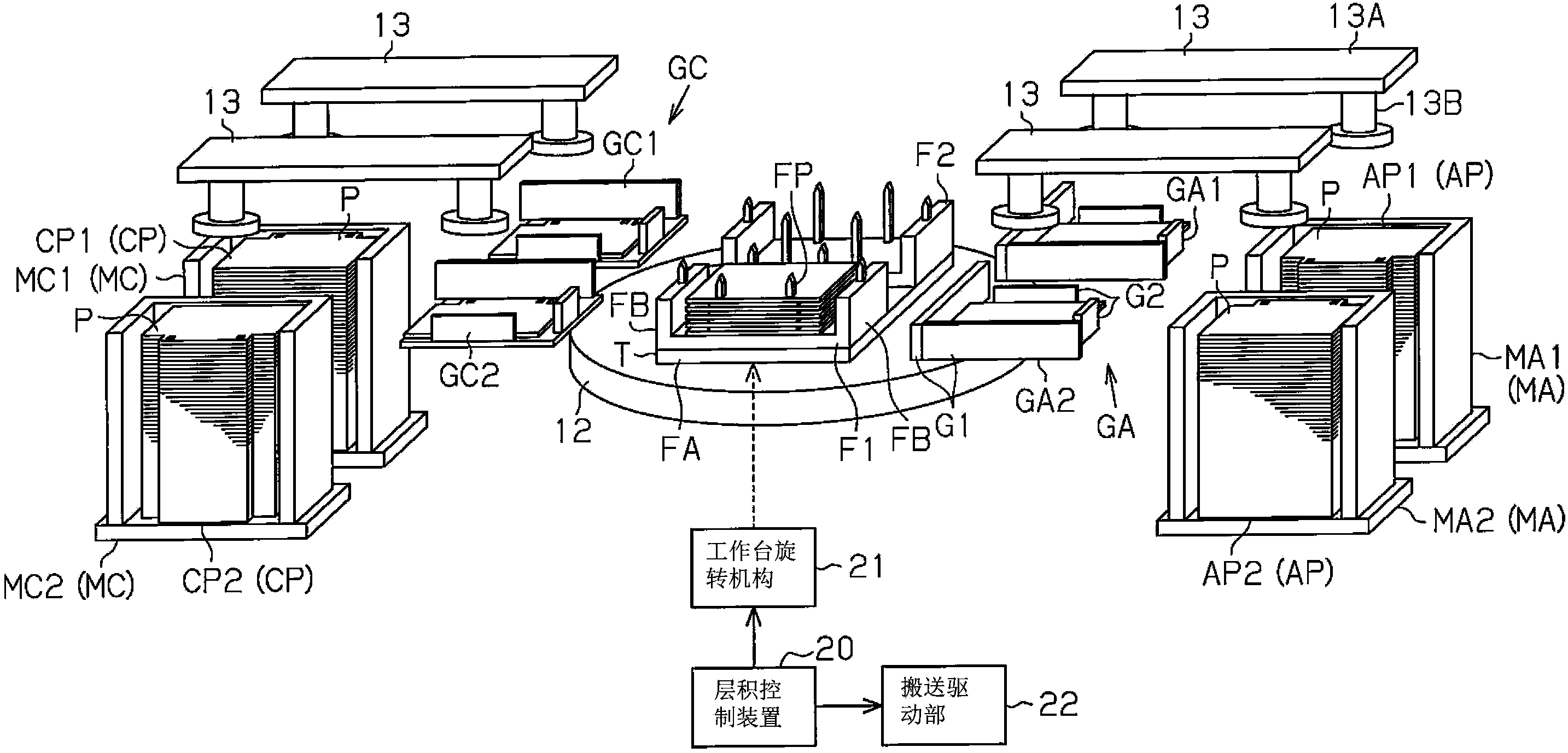
[0044] Such as figure 1 As shown, the electrode plate lamination apparatus includes a negative electrode case MA for accommodating the negative electrode plate AP and a positive electrode case MC for accommodating the positive electrode plate CP. The negative electrode plate is produced by coating a paste containing a hydrogen storage alloy powder as an active m...
no. 2 Embodiment approach
[0092] Next, a second embodiment in which the battery manufacturing apparatus and the battery manufacturing method of the present invention are embodied will be described. In addition, since the second embodiment is only a structure in which a part of the electrode plate lamination apparatus of the first embodiment is changed, many of the same parts are given the same and detailed description thereof will be omitted.
[0093] Such as Figure 6 As shown, the electrode plate lamination apparatus which is the battery manufacturing apparatus of this embodiment is equipped with the 1st table TA and the 2nd table TB on the base 12. Each table TA, TB is rotated by the table rotation mechanism 21 . In addition, the base 12 itself is also rotatably supported by the base 11 arranged below it. A base rotation mechanism 23 including a drive source and the like is connected to the base 12 . The base rotation mechanism 23 is driven by the lamination control device 20 .
[0094] First an...
no. 3 Embodiment approach
[0116] Next, a third embodiment in which the battery manufacturing apparatus and the battery manufacturing method of the present invention are embodied will be described. In addition, since the third embodiment is only a configuration in which a part of the electrode plate lamination apparatus of the first embodiment is changed, the same reference numerals are assigned to the same parts, and detailed description thereof will be omitted.
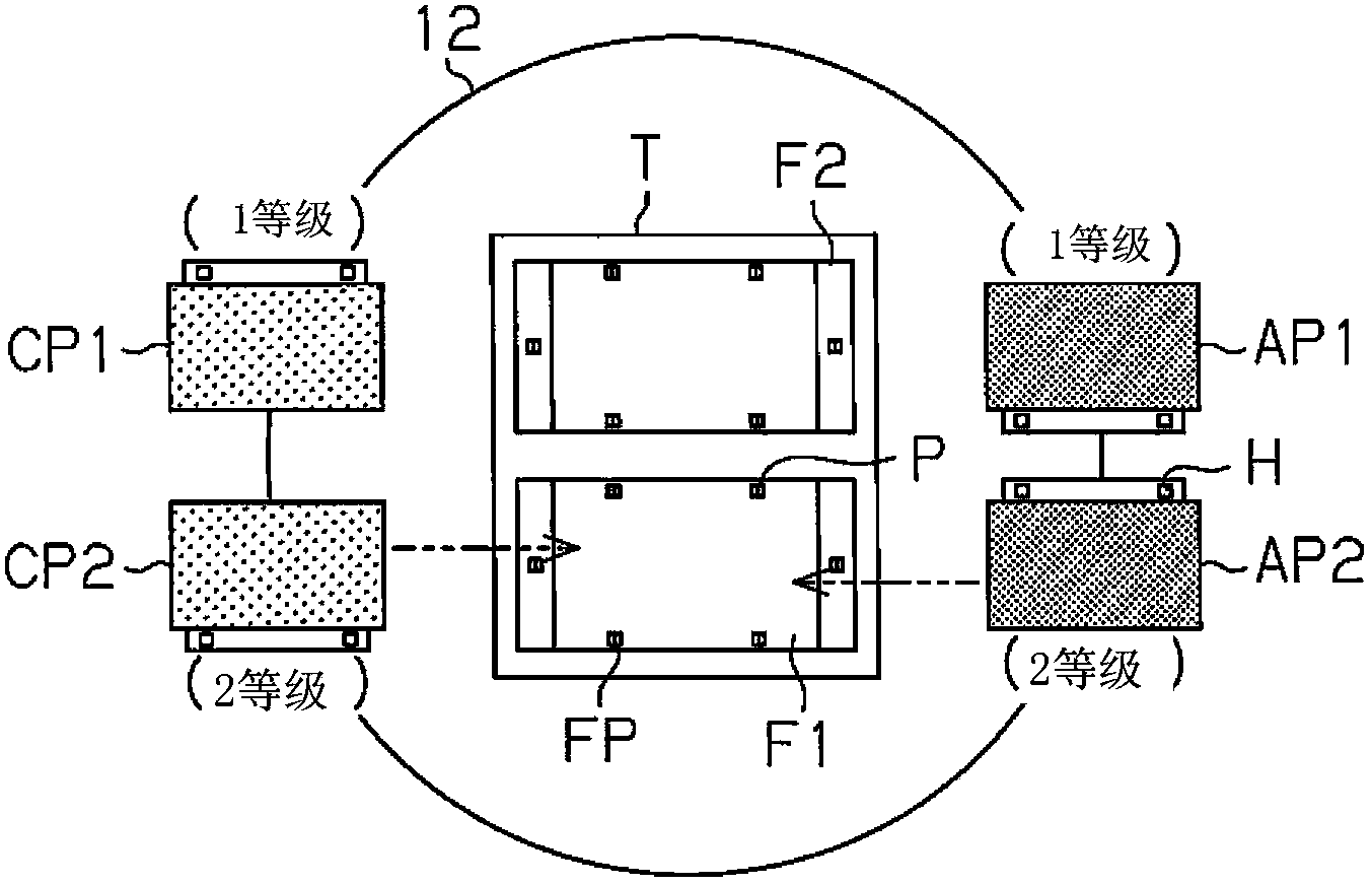
[0117] Such as Figure 16 As shown, in this embodiment, the first electrode plate mounting portion on which the negative electrode plate AP1 of the “first level” is placed and the first electrode plate mounting portion on which the positive electrode plate CP1 of the “first level” are placed are arranged at the bottom of the figure. side. In addition, the second electrode plate mounting part on which the negative electrode plate AP2 of "2nd grade" is mounted and the second electrode plate mounting part on which the positive electrode plate C...
PUM
 Abstract
Description
Claims
Application Information
 - R&D
- Intellectual Property
- Life Sciences
- Materials
- Tech Scout
- Unparalleled Data Quality
- Higher Quality Content
- 60% Fewer Hallucinations
Browse by: Latest US Patents, China's latest patents, Technical Efficacy Thesaurus, Application Domain, Technology Topic, Popular Technical Reports.
© 2025 PatSnap. All rights reserved.Legal|Privacy policy|Modern Slavery Act Transparency Statement|Sitemap|About US| Contact US: help@patsnap.com