
Movable MEMS large turning angle blazed grating light modulator based on double-layer comb drive

A blazed grating and optical modulator technology, applied in the field of MEMS optical modulators, can solve the problems of tuning frequency (low switching speed, limited tuning ability of optical modulators, small rotation angle of grating bars, etc.) Reliable performance and large rotation angle

Inactive Publication Date: 2014-07-02
CHONGQING UNIV
View PDF8 Cites 7 Cited by
  • Summary
  • Abstract
  • Description
  • Claims
  • Application Information

AI Technical Summary

Problems solved by technology

Since the electrostatic drive requires a small distance between the driving electrode and the grating surface to produce a deflection effect smaller than the breakdown voltage of the silicon chip, and due to the pull-in phenomenon, only about 1 / 3 of the stroke of this distance is available, so the rotation angle of the grating bar are relatively small, which limits the tuning capability of the optical modulator
At the same time, the driving mode of the electrostatic torsion grating strip is directly below the grating strip, which is easy to cause the grating strip to deform under the influence of stress during twisting and reduce the diffraction efficiency.
Moreover, when the grating strip is pulled down by static electricity, it is easy to cause the grating strip to adhere to the bottom surface due to the phenomenon of suction and cause failure.
There are also tunable blazed gratings driven by an external magnetic field or SMA (shape memory alloy), but the driving method limits its tuning frequency (switching speed) to low

Method used


Image

  • Movable MEMS large turning angle blazed grating light modulator based on double-layer comb drive
  • Movable MEMS large turning angle blazed grating light modulator based on double-layer comb drive

Examples


Embodiment Construction

[0024] Preferred embodiments of the present invention will be described in detail below.

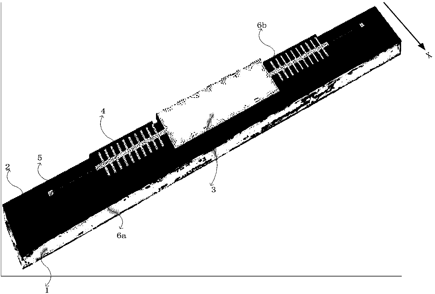
[0025] see figure 1 In this embodiment, the silicon substrate 1 of the double-layer comb driven MEMS large-rotation-angle movable blazed grating optical modulator and the insulating layer 2 disposed on the silicon substrate 1, the grating mirror surface 3 is suspended and supported on the insulating layer 2 by torsion beams Above, the torsion beam is composed of movable teeth 4 and pillars 5, electrodes are arranged on the movable teeth 4, one end of the movable teeth 4 is fixed on the insulating layer 2 through the pillars 5, and the other end of the movable teeth 4 is fixed to the grating mirror 3 connection, the movable teeth are two, fixedly connected with the two ends of the grating mirror 3 respectively, the movable teeth 4 and the fixed teeth 6 form a comb driver, wherein the fixed teeth 6 are fixed on the substrate 1, and electrodes are arranged on it , there are two fixed teeth...


PUM


Abstract

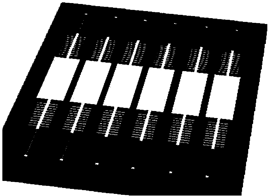
The invention relates to the technical field of MEMS light modulators, in particular to an MEMS blazed grating light modulator and an array. Double-layer comb drive is adopted by the movable MEMS large turning angle blazed grating light modulator and the double-layer comb drive position is located on flexible support beams at the two ends of an optical grating mirror face. When a plurality of movable blazed grating light modulators are used for forming the array, each movable MEMS large turning angle blazed grating light modulator under double-layer comb drive can be controlled by a drive circuit to independently work and a gap between every two optical grating mirror faces is small. According to the structure, an optical grating can be made to deflect to the two sides at a large angle and has the advantages of being large in deflection angle, high in diffraction efficiency, high in tuning frequency and resistant to adhesion. The optical grating light modulator and the array of the optical grating light modulators can be applied to the fields of spectrometers, optical communication, accurate measurement, laser shaping, displaying and the like.

Description

technical field [0001] The invention relates to the technical field of MEMS light modulators, in particular to a MEMS blazed grating light modulator and an array. Background technique [0002] When the grating is carved into a sawtooth-shaped groove section, the light energy is concentrated on a certain spectral level. When detected in this direction, the maximum spectral intensity can be obtained. This phenomenon is called blazed, and this kind of grating is a blazed grating. In a blazed grating, a smooth plane plays the role of diffraction, and it has an angle with the grating surface, called the blaze angle. The blazed grating has the characteristics of zero-order light splitting and high diffraction efficiency, so its research has attracted more and more attention. Blazed gratings can be used in spectrometers, optical communications, precision measurement, laser shaping, display and other fields. [0003] Once the optical device array of the traditional blazed grating...

Claims


Application Information

Patent Timeline
IPC IPC(8): G02B26/08B81B3/00
Inventor 张智海张文凯路远高玲肖
Owner CHONGQING UNIV
Learn More