
Rubble stone stack and reinforced soil composite embankment culvert pipe structure

A technology for reinforcing embankments and rubble piles, which is applied to the bottom layer of roads, buildings, etc., can solve problems such as difficulty in installing culverts on rubble embankments, reduce construction costs, and fall deformation, and achieve coordination of uneven settlement, improved stress state, and cost low effect

Active Publication Date: 2014-07-02
佳风工程设计有限公司
View PDF8 Cites 2 Cited by
  • Summary
  • Abstract
  • Description
  • Claims
  • Application Information

AI Technical Summary

Problems solved by technology

However, when building an embankment with a height of more than 10 meters using the traditional flexible reinforced embankment, the minimum width is required to be more than 7 meters, so it is difficult to construct in the narrow part of the slope foot of the steep slope section (the width is less than 7 meters)
[0004] Radar base stations are often built on local slopes with relatively high heights. These slopes often have a large number of slope-accumulated boulders and boulders. Using local materials to build flake embankments with boulders and boulders can reduce construction costs. When construction is carried out at the narrow part of the foot of the steep slope (with a width less than 7 meters), but the height is greater (greater than 7 meters), the slope of the embankment of the steep slope is prone to fall or deformation of the rubble, and it is difficult to install culverts on the embankment of the rubble

Method used


Image

  • Rubble stone stack and reinforced soil composite embankment culvert pipe structure

Examples


Embodiment Construction

[0012] The present invention will be further described below with reference to the drawings and specific embodiments.

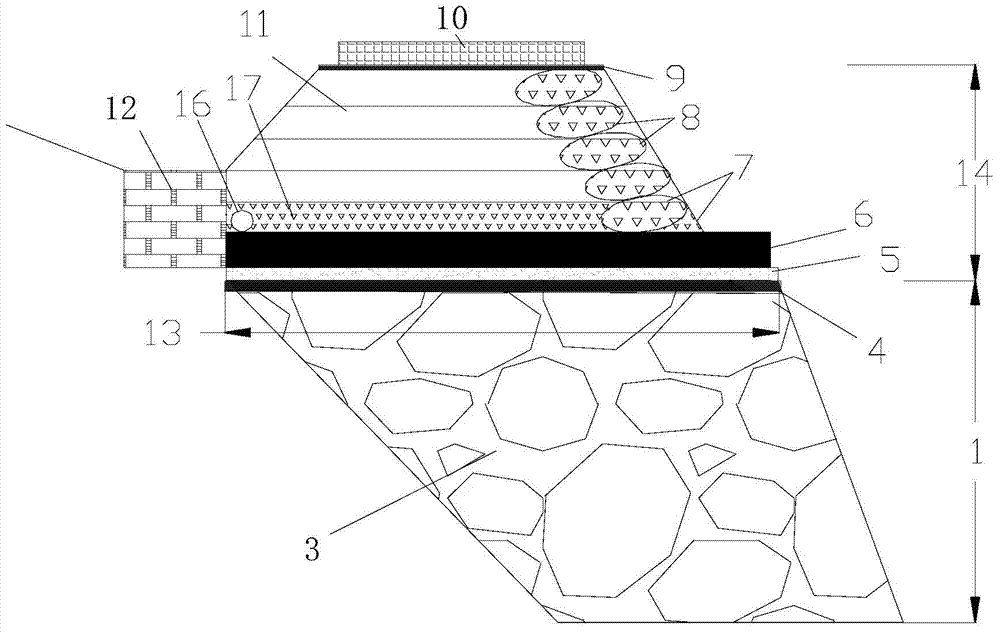
[0013] See figure 1 , The rubble embankment 3 shall be constructed according to the conventional rubble embankment, the height 1 of the rubble embankment 3 is not more than 8 meters, the top width 13 is greater than 7 meters, and the embankment surface of the rubble embankment 3 maintains an inwardly inverted embankment greater than 5% The slope rate, the upper part of the rubble embankment 3 is provided with the first impervious geotextile 4, the upper part of the first impervious geotextile 4 is provided with a cushion layer 5 made of sand and gravel, and a culvert pipe 6 is arranged on the cushion layer 5. A sinkhole 12 is provided on the side close to the natural slope, and the culvert pipe 6 is connected to the sinkhole 12. Above the culvert pipe 6 is provided a set of gravel soil 17 and a soft permeable pipe 16 placed on the side close to the natural slope...


PUM

PropertyMeasurementUnit
Heightaaaaaaaaaa
Widthaaaaaaaaaa

Abstract

The invention discloses a rubble stone stack and reinforced soil composite embankment culvert pipe structure which comprises a bottom rubble stone stack embankment, middle culvert pipes and an upper flexible reinforced soil embankment. The rubble stone stack embankment is the same as a conventional rubble stone stack, however, the top width of the rubble stone stack embankment is expected to be larger than 7 meters, the height of the rubble stone stack embankment is expected not to be larger than 8 meters, the flexible reinforced soil embankment is consistent with a conventional reinforced soil embankment, however, the bottom width of the flexible reinforced soil embankment is larger than 7 meters, the height of the flexible reinforced soil embankment is smaller than 6 meters, impervious geotextile is arranged on the top and at the bottom of the flexible reinforced soil embankment, and the bottom of the flexible reinforced soil embankment is provided with a drainage layer composed of flexible permeable hoses and gravel soil; sand sediment traps are arranged on the side close to natural side slopes. According to the rubble stone stack and reinforced soil composite embankment culvert pipe structure, the characteristic that the flexible reinforced soil embankment improves differential settlement of the culvert pipe and improves the longitudinal stress state of the culvert pipe is maintained, the advantage that the rubble stone stack embankment is easy to construct in a narrow position of a slope toe and low in cost is also maintained, and the rubble stone stack and reinforced soil composite embankment culvert pipe structure is mainly applied to maintain streams of low-cost roads for reaching the peak.

Description

Technical field [0001] The invention relates to an embankment culvert pipe structure, in particular to a composite embankment culvert pipe structure reinforced by rubble piles. Background technique [0002] Radar base stations are often built on the top of small hills, and simple roads to the top are often needed for this. When the simple road to the top meets a mountain stream, it cannot be crossed by the construction of a small bridge due to road construction cost restrictions. The most economical method is to use the construction of rubble retaining walls and embankment culverts. Due to the scouring effect of the stream in the mountain stream, the base part of the stone retaining wall to be built is often soft soil. After the soft soil is removed, the site of the stone retaining wall to be built is usually a height of more than 10 meters. For steep slope sections with narrow toe, construction of rubble retaining walls and embankment culvert pipes in this case will not only gr...

Claims


Application Information

Patent Timeline
IPC IPC(8): E01F5/00
Inventor 刘龙武
Owner 佳风工程设计有限公司
Learn More