Eureka AIR delivers breakthrough ideas for toughest innovation challenges, trusted by R&D personnel around the world.

Dyeing machine

A dyeing machine and dyeing solution technology, applied in the field of dyeing machines, can solve problems such as prolonging dyeing time, lowering dyeing rate, and longer dyeing time, and achieve the effects of improving dyeing efficiency, reducing liquor ratio, and reducing emissions

Inactive Publication Date: 2014-07-02
NINGBO EASTSUN TEXTILES
View PDF6 Cites 10 Cited by
  • Summary
  • Abstract
  • Description
  • Claims
  • Application Information

AI Technical Summary

Problems solved by technology

In order to reduce the discharge of waste water, the bath ratio must be reduced. For this reason, the inventor has applied for another patent so that the fabric does not need to be soaked in the dye solution in the bottom tank, which greatly reduces the bath ratio, but this makes the coloring of the dyeing The dyeing rate is reduced, and the dyeing time becomes longer. For this reason, the inventor has designed a device that can ensure the dyeing rate without being soaked in the dyeing solution, and does not need to prolong the dyeing time.

Method used

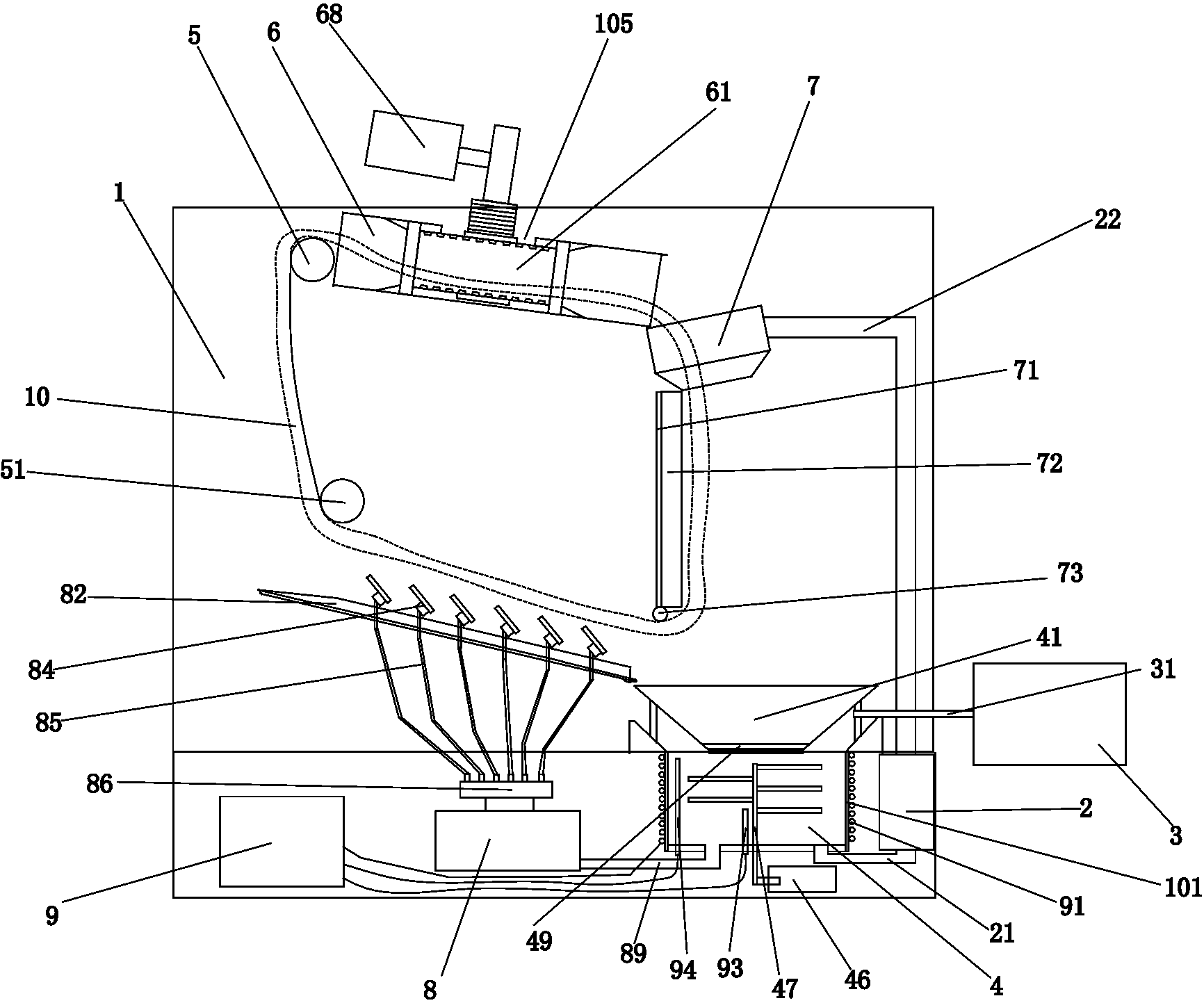

Image

  • Dyeing machine
  • Dyeing machine
  • Dyeing machine

Examples


Embodiment Construction

[0014] The present invention will be further described in detail below in conjunction with the accompanying drawings and specific embodiments.

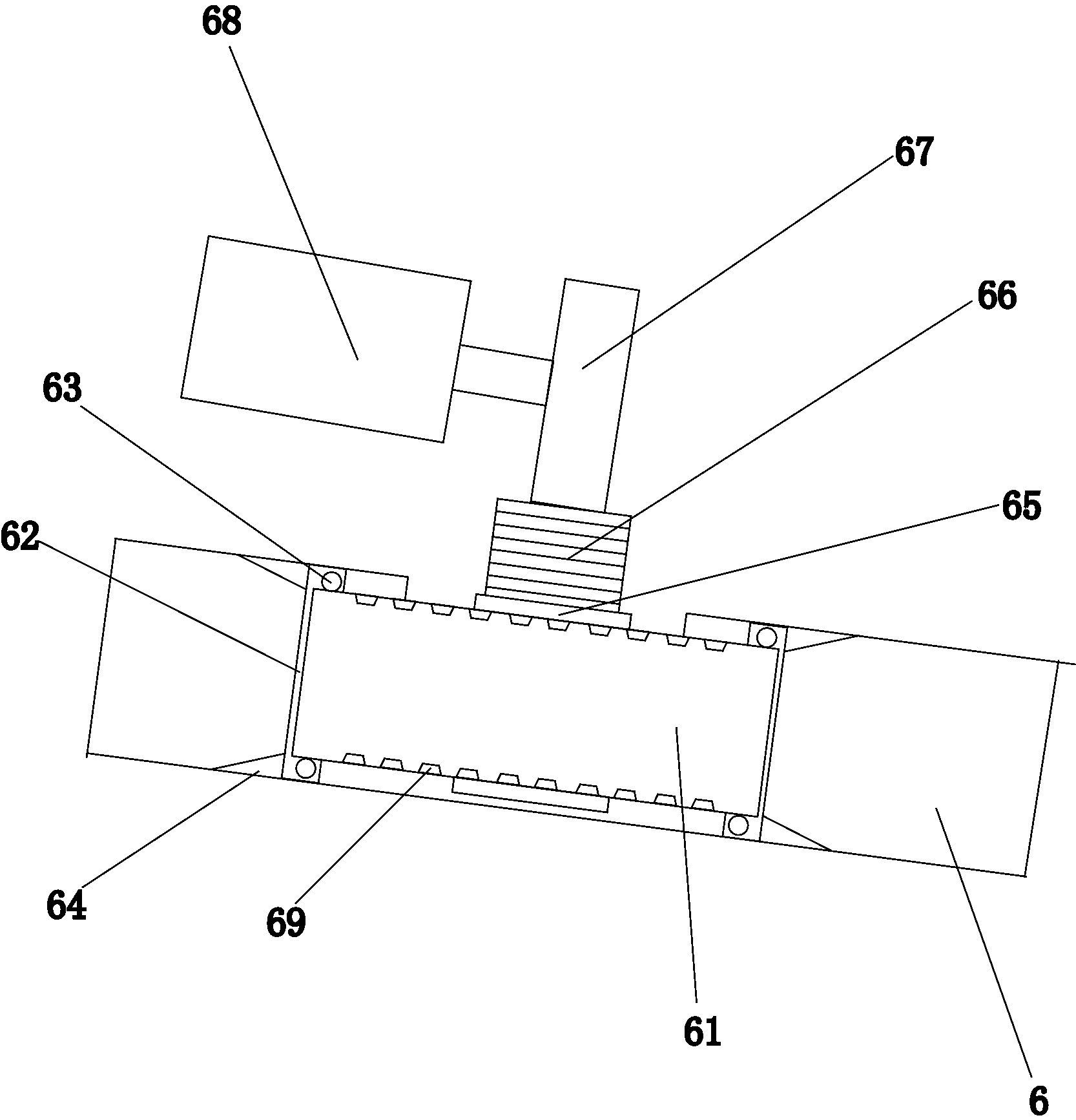
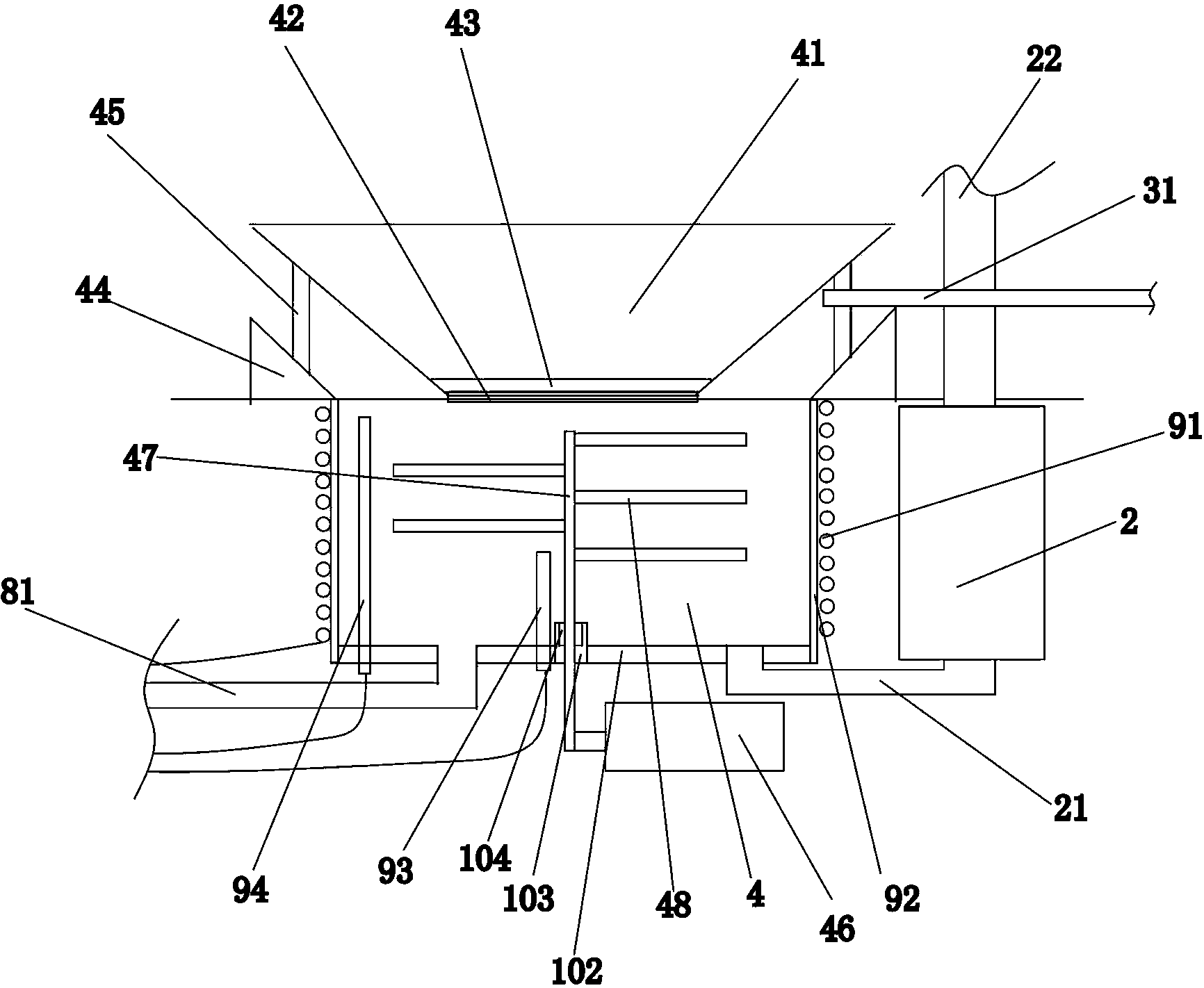
[0015] Such as figure 1 , figure 2 , image 3 with Figure 4 As shown, a dyeing machine includes a cylinder body 1, a circulation pump 2, and a dye solution tank 3. A cloth lifting wheel 5, a cloth guide pipe 6, and a large nozzle 7 are arranged in the cylinder body 1. The bottom of the cylinder body 1 is provided with a groove 4, the groove 4 is located directly below the large nozzle 7, the groove 4 includes a circular iron side wall 101 and a bottom plate 102 made of ceramic material, and the side wall 101 is wrapped with an insulating material 92. The thermal insulation material 92 can be thermal insulation cotton, or other thermal insulation materials. An electromagnetic coil 91 is arranged around the insulating material 92 , and the electromagnetic coil 91 surrounds and wraps the side wall 101 . The bottom of the groove 4 ...


PUM


Abstract

The invention provides a dyeing machine, and relates to a textile fabric dyeing machine. The dyeing machine comprises a tank, a circulating pump and a dye liquor box. A large nozzle, a cloth guide pipe and a cloth lifting wheel are arranged in the tank. The dyeing machine is characterized in that a roller is rotationally arranged in the cloth guide pipe, an annular rack is arranged on the roller, an opening matched with the annular rack is formed in the cloth guide pipe, a motor is arranged outside the tank, a gear matched with the annular rack is arranged in the tank, the motor is in transmission connection with the gear, and a plurality of tidily-arranged protrusions are arranged in the roller. Compared with the prior art, textile fabric in the dyeing machine can be automatically turned over, the contact area of the textile fabric and dye liquor is increased, the textile fabric is fully soaked in the dye liquor, dyeing efficiency is improved, meanwhile, the bath ratio is reduced, and drainage of waste water is reduced.

Description

technical field [0001] The invention belongs to a kind of dyeing equipment, in particular to a kind of dyeing machine. Background technique [0002] The dyeing machine has many uses, for example, it can be mainly used for dyeing, bleaching, scouring and washing of woolen sweaters, acrylic and cotton sweaters, etc. It can also be used for bleaching and dyeing of gloves, socks, towels and other finished products. A kind of bleaching and dyeing equipment suitable for a wide range. The main working principle of the dyeing machine is to use the circulation pump to promote the circulation of the dye liquor along the pipeline, and the temperature of the dye liquor is raised to 130°C-135°C through the heat exchanger assembly, and then flows through the filter assembly to filter and flow to the nozzle assembly, the nozzle assembly The dyeing liquid is sprayed onto the fabric under the pressure drive, and the fabric is pushed into the cloth guide pipe. The dye liquid passes through t...

Claims


Application Information

Patent Timeline
Patent Type & Authority Applications(China)
IPC IPC(8): D06B1/02D06B23/04
Inventor 周秋月
Owner NINGBO EASTSUN TEXTILES
Why Eureka
Eureka Blog
Learn More