Built-in tangential permanent magnet steel hub driving motor of electric vehicle

A technology for electric vehicles and drive motors, applied in electric vehicles, motors, synchronous motors with stationary armatures and rotating magnets, etc., can solve the problems of high energy consumption, high power consumption, and low output power of DC motors, and achieve The effect of low power consumption, low failure rate and high power density

Inactive Publication Date: 2014-06-25
SHANDONG UNIV OF TECH
View PDF4 Cites 5 Cited by
  • Summary
  • Abstract
  • Description
  • Claims
  • Application Information

AI Technical Summary

Problems solved by technology

[0002] At present, most of the driving motors used with electric vehicles are DC motors with carbon brushes and mechanical commutators. Although DC motors have simple structure, high controllability, wide speed range, relatively simple control circuit, and low cost, but Since the magnetic field of the DC drive motor is generated by the electric excitation winding, the power consumption is large and the output power is small. In addition, due to the existence of carbon brushes and mechanical commutators, it not only limits the improvement of the overload capacity and speed of the drive motor, but also if it runs for a long time, it is bound to Frequent maintenance and replacement of carbon brushes and commutators is required, so the DC motor consumes a lot of energy and has a high failure rate, and its performance needs to be further improved

Method used


Image

  • Built-in tangential permanent magnet steel hub driving motor of electric vehicle
  • Built-in tangential permanent magnet steel hub driving motor of electric vehicle

Examples


Embodiment Construction

[0011] The present invention will be further described below in conjunction with accompanying drawing:

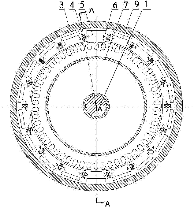
[0012] The electric vehicle embedded tangential permanent magnet steel wheel hub drive motor composed of shaft 1, front end cover 2, rear end cover 8, hub type casing 3, rotor, stator 6, and stator bracket 7 is characterized in that: the hub drive motor rotor It is a permanent magnet rotor embedded with tangential permanent magnet steel;

[0013] The permanent magnet rotor embedded with tangential permanent magnet steel is composed of rotor iron core 5, rectangular permanent magnet steel 4, and hub-type casing 3. On the rotor iron core 5, there are even numbers of radial rectangles penetrating the thickness of the rotor iron core 5. Slot, the inner end of the radial rectangular slot is not connected with the inner circle of the rotor core 5, the distance between the disconnected part is 1.5mm, and the rotor core is provided between the outer ends of two adjacent radial rect...


PUM


Abstract

The invention provides a built-in tangential permanent magnet steel hub driving motor of an electric vehicle and belongs to the technical field of automobile motor electric appliances. The built-in tangential permanent magnet steel hub driving motor of the electric vehicle consists of a shaft, a front end cover, a rear end cover, a hub casing, a rotor, a stator and a stator support. A first piece of rectangular permanent magnet steel and the other piece of rectangular permanent magnet steel are sequentially installed in radial rectangular grooves of a rotor iron core in a mode that an N-pole of the first piece of rectangular permanent magnet steel is opposite to an N-pole of the other piece of rectangular permanent magnet steel, and an S-pole of the first piece of rectangular permanent magnet steel is opposite to an S-pole of the other piece of rectangular permanent magnet steel, a tangential permanent magnet rotor with N-poles and S-poles arranged at intervals is formed, the structure is a rotor magnetic bypass structure and can effectively prevent the permanent magnet steel from producing irreversible demagnetization under the armature reaction effect of impact current, and excitation loss of the permanent magnet steel is ensured. A rotor magnetic field of the hub driving motor is provided by the permanent magnet steel without electro-magnetic windings, electric energy consumption is low, carbon brushes and mechanical commutators are not adopted, the failure rate is low, and the built-in tangential permanent magnet steel hub driving motor has high-efficiency, high-power-density and remarkable magnetic focusing effect and can provided enough power for the electric vehicle.

Description

technical field [0001] The invention provides a driving motor embedded with a tangential permanent magnet steel hub for an electric vehicle, which belongs to the technical field of automobile motors and electrical appliances. Background technique [0002] At present, most of the driving motors used with electric vehicles are DC motors with carbon brushes and mechanical commutators. Although DC motors have simple structure, high controllability, wide speed range, relatively simple control circuit, and low cost, but Since the magnetic field of the DC drive motor is generated by the electric excitation winding, the power consumption is large and the output power is small. In addition, due to the existence of carbon brushes and mechanical commutators, it not only limits the improvement of the overload capacity and speed of the drive motor, but also if it runs for a long time, it is bound to Frequent maintenance and replacement of carbon brushes and commutators is required, so th...

Claims


Application Information

Patent Timeline
Patent Type & Authority Applications(China)
IPC IPC(8): H02K21/24
CPCY02T10/64
Inventor 张学义杜钦君马清芝高松尤迪
Owner SHANDONG UNIV OF TECH
Why Eureka
Try Eureka