
SF6 gas decomposed product detection device and method based on photoacoustic spectrometry technology

A technology of gas decomposition and photoacoustic spectroscopy, which is used in measurement devices, material analysis by optical means, and material analysis, etc., can solve the problem that the measurement accuracy is difficult to meet the diagnosis of latent faults of SF6 equipment, the detection results are inaccurate, and the maintenance cost is high. problems, to achieve the effect of improving work reliability, reducing system noise, and having a simple and compact structure

Inactive Publication Date: 2014-06-25
STATE GRID CORP OF CHINA +1
View PDF7 Cites 13 Cited by
  • Summary
  • Abstract
  • Description
  • Claims
  • Application Information

AI Technical Summary

Problems solved by technology

At present, the detectors used in the industry mainly use the electrochemical sensor detection method. During the detection process, this kind of sensor is "poisoned" by the influence of sulfide corrosion, which is prone to drift or damage, resulting in inaccurate detection results, and its measurement accuracy is difficult to meet. Requirements for diagnosing latent faults of SF6 equipment, while maintaining high maintenance costs and high failure rates

Method used


Image

  • SF6 gas decomposed product detection device and method based on photoacoustic spectrometry technology
  • SF6 gas decomposed product detection device and method based on photoacoustic spectrometry technology
  • SF6 gas decomposed product detection device and method based on photoacoustic spectrometry technology

Examples


Embodiment Construction

[0028] Embodiments of the present invention are further described below in conjunction with accompanying drawings:

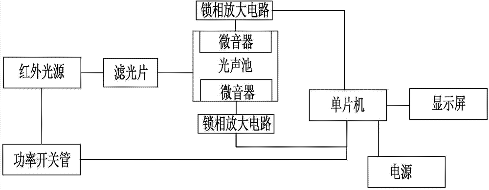
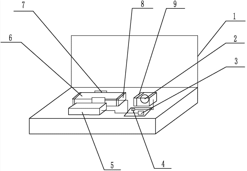
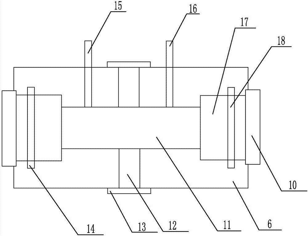
[0029] Such as figure 1 , figure 2 , image 3 , Figure 4 As shown, the SF6 gas decomposition product detection device based on photoacoustic spectroscopy technology of the present invention includes a housing 1, a single-chip microcomputer 3 and its auxiliary circuit are arranged inside the housing 1, the single-chip microcomputer 3 and its auxiliary circuit are connected to the power supply 5, and the single-chip microcomputer 3 The infrared light source 2 is connected to the infrared light source 2 through the power switch tube 4, and the infrared light source 2 is opposite to the light source entrance 8 of the photoacoustic pool 6. A resonant cavity 11 is arranged inside the photoacoustic pool 6, and a circular ring communicating with the resonant cavity 11 is arranged on both sides of the photoacoustic pool 6. Hole 7, microphone 12 is installed in the c...


PUM


Abstract

The invention relates to the field of detection of gas decomposed products and particularly relates to an SF6 gas decomposed product detection device and an SF6 gas decomposed product detection method based on a photoacoustic spectrometry technology. The SF6 gas decomposed product detection device comprises a shell, wherein the shell is internally provided with a single chip microcomputer and an accessory circuit thereof; the single chip microcomputer and the accessory circuit thereof are connected with a power supply; the single chip microcomputer is connected with an infrared light source by a power switch tube; the infrared light source is arranged opposite to a light source entrance port of a photo-acoustic cell; the photo-acoustic cell is internally provided with a resonant cavity; circular holes communicated with the resonant cavity are formed in the two sides of the photo-acoustic cell; microphones are mounted in the circular holes in the two sides; the microphones are connected with the single chip microcomputer by lock phase amplification circuits; the single chip microcomputer is connected with a display screen; an air inlet and an air outlet which are communicated with the resonant cavity are arranged at the upper end of the photo-acoustic cell. According to the SF6 gas decomposed product detection device and method, the problems of cross interference and electrode poisoning in an electrochemical method are avoided; the system noise is lowered, the detection accuracy is improved, the structure is simple and compact, the volume is small and the stability is good.

Description

technical field [0001] The invention relates to the field of detection of gas decomposition products, in particular to a detection device and method for SF6 gas decomposition products based on photoacoustic spectroscopy technology. Background technique [0002] With the rapid development of smart grids, electrical equipment using SF6 gas as an insulating medium has been widely used, and the detection of SF6 gas decomposition products is an effective method for diagnosing the operating conditions and latent faults of SF6 equipment. The sulfides produced by the decomposition of SF6 electrical equipment during internal faults mainly include SO2, H2S, SF4, SO2F SOF2, S2F10, and S2OF10; the fluorides mainly include HF, CF4, AlF3, CuF2, and WF6; the carbides mainly include CO, CO2, and low molecular weight hydrocarbons etc. Among them, the three components of SO2, H2S and CO can be used as the characteristic components for analysis and judgment when the equipment fails. At prese...

Claims


Application Information

Patent Timeline
IPC IPC(8): G01N21/3504
Inventor 赵利岳增伟阎炳水耿宁徐天锡杨静李天林英崔川季素云孙学锋李志刚张涛高鹏王毅王晔王世儒孙立新王建民张杰乔恒
Owner STATE GRID CORP OF CHINA
Learn More