
Guiding type corrugated limiter

A guide type, limiter technology, applied in the direction of pipes/pipe joints/pipes, expansion compensation devices for pipelines, mechanical equipment, etc., can solve the problems of excess flexibility and insufficient anti-rotation ability, and achieve strong compressive ability. , Significant anti-torsion effect, easy to make

Inactive Publication Date: 2014-06-25
JIANGSU SHUGUANG PRESSURE VESSEL
View PDF8 Cites 2 Cited by
  • Summary
  • Abstract
  • Description
  • Claims
  • Application Information

AI Technical Summary

Problems solved by technology

[0003] The present invention mainly aims at the problem that the prior art products have more than enough flexibility and insufficient anti-rotation ability, and propose a guided corrugated stopper suitable for supporting heavy equipment. The bellows in the stopper have a reasonable structure, both rigidity and flexibility, and flexible compensation , Strong pressure resistance, and only axial displacement under the guidance of the guide structure

Method used


Image

  • Guiding type corrugated limiter
  • Guiding type corrugated limiter
  • Guiding type corrugated limiter

Examples


Embodiment Construction

[0017] The present invention will be further described below according to the accompanying drawings and in conjunction with the embodiments.

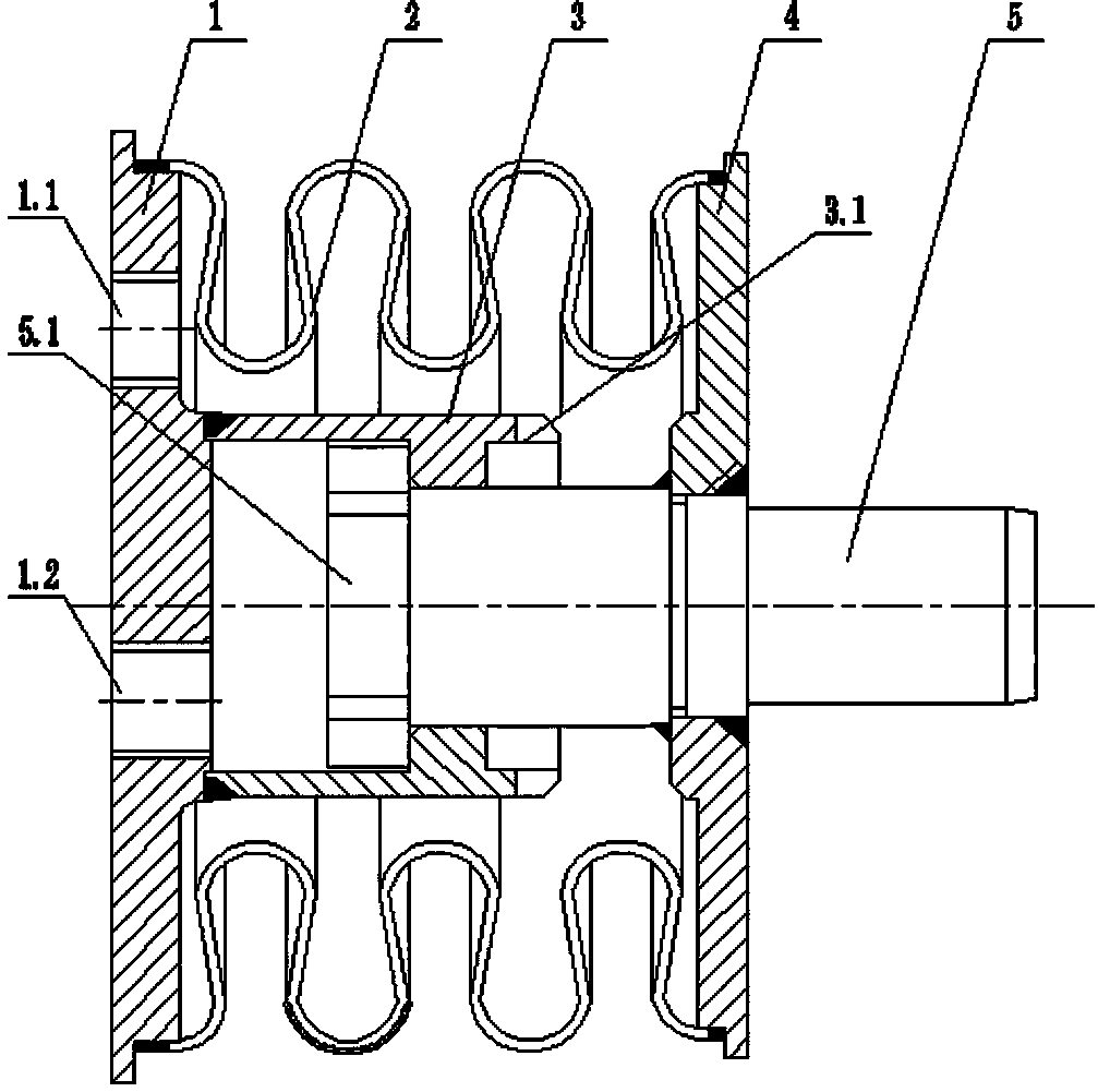
[0018] figure 1 The shown guide corrugated limiter is applied to an embodiment of a 30,000 KVA electric furnace in the iron and steel manufacturing industry. The guide sleeve 3 is a thin-walled sleeve with a built-in shoulder, and the circumference of the right port is provided with alternate gaps 3.1. The notch 3.1 is an overflow channel. In order to ensure the smooth flow of the overflow, three rectangular notches 3.1 are evenly distributed around the circumference of the right port of the guide sleeve 3 in this embodiment, and the total overflow area of ​​the three notches 3.1 is equal to one time of the area of ​​the outlet 1.2. . The built-in shoulder of the guide sleeve 3 is a concave-convex structure on the same circumference. During installation, the guide sleeve 3 is equipped with an external coaxial bellows 2, and a mandrel...


PUM


Abstract

The invention discloses a guiding type corrugated limiter which is composed of a cover plate, corrugated tubes, a guiding sleeve, a base plate and a core shaft. The guiding sleeve is a thin wall shaft sleeve internally provided with a circular bead, a notch is formed in the opening portion of the right end of the guiding sleeve, the corrugated tubes are arranged outside the centered guiding sleeve, and the core shaft is arranged in the guiding sleeve in a clearance fit mode. The cover plate is respectively connected with the left end face of the guiding sleeve and the left end faces of the corrugated tubes in a sealed mode, and the base plate is installed on the core shaft in a sleeved mode, abuts against the right end face of the guiding sleeve, and is respectively connected with the right ends of the corrugated tubes and the core shaft in a sealed mode to form a linkage structure. The circular bead arranged in the guiding sleeve is of the structure that concave portions and convex portions are alternatively arranged on the same circumference, the shape of the cross section of the large end face of the core shaft is the same as the shape of the circular bead arranged in the guiding sleeve, and the core shaft is in clearance fit with the guiding sleeve to form an anti-torque structure for straight going of the core shaft. The waveform axial sections of the corrugated tubes in the guiding type corrugated limiter are in omega shapes, the tube walls of the corrugated tubes are smooth, thick, reasonable in stress and even in elastic deformation, limitation is accurate, and the corrugated tubes are particularly suitable for working under the high-temperature and high-pressure working conditions.

Description

technical field [0001] The present invention relates to a pipeline safety device, in particular, the present invention relates to a limit device relying on the elastic deformation of a bellows, especially a bellows limiter limited to axial compensation. Background technique [0002] The 30,000 KVA electric furnace used in the iron and steel manufacturing industry is a heavy-duty equipment. The hydraulic power system is high-temperature and high-pressure. Frequent movements in the production process cause unequal internal stresses in the connecting pipes between adjacent equipment. Among them, the most destructive Internal stress is axial thrust. In order to ensure safe production, corresponding pipe stoppers must be installed in the connecting pipes between these devices to absorb the axial thrust. The supporting pipe stoppers in engineering usually use U-shaped, S-shaped and V-shaped bellows as elastic elements. Although the bellows used in the prior art products are suff...

Claims


Application Information

Patent Timeline
IPC IPC(8): F16L51/02
CPCF16L51/025
Inventor 谢小霞游小冬
Owner JIANGSU SHUGUANG PRESSURE VESSEL
Learn More