Bulldozer and hydraulic system thereof

A hydraulic system and bulldozer technology, applied in the hydraulic field, can solve the problems of reducing assembly efficiency, causing system failure, unable to take into account hydraulic oil pollution, etc., and achieving the effect of improving the purity of oil and improving assembly efficiency

Inactive Publication Date: 2014-06-25
SHANTUI CONSTR MASCH CO LTD
View PDF9 Cites 2 Cited by
  • Summary
  • Abstract
  • Description
  • Claims
  • Application Information

AI Technical Summary

Problems solved by technology

[0009] First, in order to minimize the oil filtering time, the oil flow of the online filter system is generally relatively large. However, the hydraulic oil in the oil tank 3 is limited and cannot be used for the online filter system and the variable speed steering system to work at the same time. Therefore, it can only be used after the test run. Finally, after the actuator 4 of the variable speed steering system stops operating, the online filter system is turned on again. In this way, the oil filter process takes up the assembly time before the equipment leaves the factory and reduces its assembly efficiency.
[0010] Second, the online filtration system is a special tool, driven by a dedicated host, and installed outside the equipment, which is specially used to filter the fuel tank 3 before leaving the factory, and cannot take into account the second type of pollution caused by the above-mentioned pollution sources after leaving the factory Contamination of the hydraulic oil, resulting in system failures when the equipment is in normal use

Method used


Image

  • Bulldozer and hydraulic system thereof
  • Bulldozer and hydraulic system thereof
  • Bulldozer and hydraulic system thereof

Examples


Embodiment Construction

[0039] In order to enable those skilled in the art to better understand the technical solutions of the present invention, the present invention will be further described in detail below in conjunction with the accompanying drawings and specific embodiments.

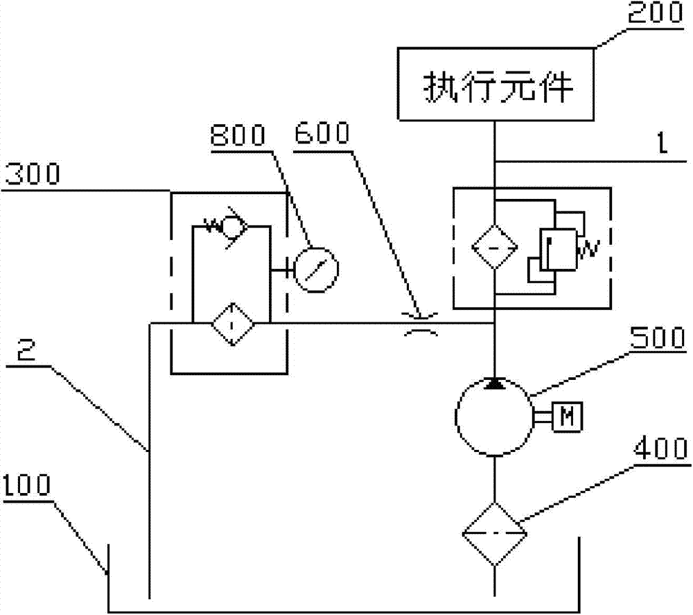
[0040] Please refer to image 3 , image 3 It is the hydraulic principle diagram of the first specific embodiment of the hydraulic system provided by the present invention.

[0041] like image 3 As shown, the hydraulic system provided by the present invention includes a main oil circuit 1 communicating with the actuator 200 and the oil tank 100, the main oil circuit 1 is supplied with oil by the hydraulic pump 500, and the oil outlet of the hydraulic pump 500 is connected to the oil tank 100 with a filter The oil filter circuit 2 is connected with the first oil filter 300 , and the oil flow rate of the oil filter circuit 2 should be smaller than that of the main oil circuit 1 .

[0042] After the oil in the oil tank 1...


PUM


Abstract

The invention discloses a hydraulic system. The hydraulic system is provide with a main oil channel which is used for communicating an oil tank and an execute component, a hydraulic pump supplies oil for the main oil channel, an oil outlet of the hydraulic pump and the oil tank are communicated through a filter oil channel, flow quantity of the filter oil channel is less than flow quantity of the main oil channel, and the filter oil channel is communicated with a first oil filter. When oil in the oil tank circularly flows through the filter oil channel, oil impurities flowing out of the oil tank are blocked in the first oil filter and cannot flow back to the oil tank again along with the oil, so that purity of the oil flowing back to the oil tank through the filter oil channel is improved; oil at the oil outlet of the hydraulic pump automatically shunts and flows toward the filter oil channel and the main oil channel according to the corresponding flow quantity, therefore, real-time filtering of the oil is achieved without affecting regular work of the execute component of the main oil channel in a same hydraulic system.

Description

technical field [0001] The invention relates to the field of hydraulic technology, in particular to a hydraulic system and a bulldozer with the hydraulic system. Background technique [0002] Contamination of hydraulic oil is one of the main causes of failure of hydraulic system and failure of actuators to work normally. [0003] Most hydraulic systems are open systems, and the sources of oil pollution can be divided into the following two categories: first, a large amount of mechanical impurities are produced during the assembly process and test run before leaving the factory, and the impurities are brought into the hydraulic system; Second, in the process of using after leaving the factory, mechanical impurities will also be generated due to the wear and tear of the gear transmission system and hydraulic components. The mechanical impurities enter the hydraulic system together with moisture and dust in the outside air. Will deteriorate and contaminate the oil. It can be ...

Claims


Application Information

Patent Timeline
Patent Type & Authority Applications(China)
IPC IPC(8): F15B21/04F15B21/08E02F3/85
Inventor 张小亮王萌陈鹏宇刘媛媛刘坤姜立勇张中元
Owner SHANTUI CONSTR MASCH CO LTD
Why Eureka
Try Eureka