Ultrasonic transducer
A transducer and ultrasonic technology, applied in the direction of piezoelectric/electrostrictive transducers, sensors, sensor types, etc., can solve the problems of damaged acoustic wave characteristics of the matching layer, unstable acoustic wave characteristics, poor durability, etc., to achieve The effect of stabilizing the acoustic wave characteristics, realizing the acoustic wave characteristics, and increasing the vibration area
- Summary
- Abstract
- Description
- Claims
- Application Information
AI Technical Summary
Problems solved by technology
Method used
Image

Examples
no. 1 Embodiment approach 》
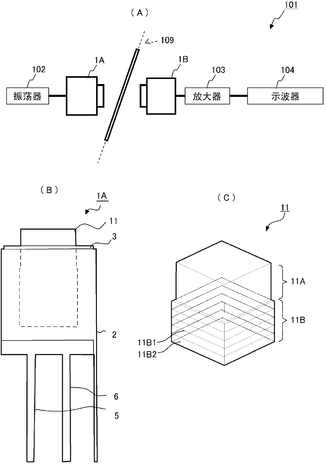
[0032] Below, based on figure 1 Next, the configurations of the ultrasonic transducer, the vibrator, and the multiple supply detection sensor according to the first embodiment of the present invention will be described.
[0033] figure 1 (A) is a conceptual diagram of the multiple feed detection sensor 101 using the ultrasonic transducers 1A and 1B according to the first embodiment of the present invention.
[0034] The multiple supply detection sensor 101 includes an ultrasonic transducer 1A for wave transmission and an ultrasonic transducer 1B for wave reception. In addition, an oscillator 102 connected to the ultrasonic transducer 1A, an oscilloscope 104 connected to the ultrasonic transducer 1B, and an amplifier 103 connected between the ultrasonic transducer 1B and the oscilloscope 104 are provided. The ultrasonic transducer 1A and the ultrasonic transducer 1B are arranged to face each other on both sides of a paper conveyance path 109 in a printing machine or the lik...
no. 2 Embodiment approach 》
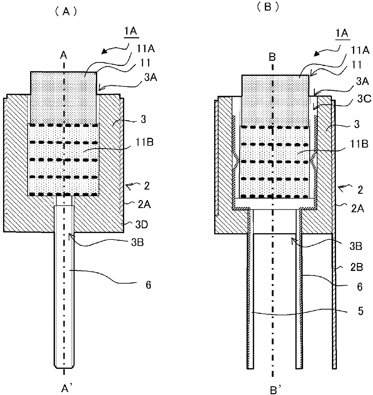
[0058] Figure 5 It is a cross-sectional view of the ultrasonic transducer 21 according to the second embodiment of the present invention. Figure 5 (A) is through Figure 5 (B) Cross-sectional view at the position of the dashed-dotted line BB'. Figure 5 (B) is through Figure 5 A cross-sectional view at the position of the one-dot chain line A-A' shown in (A).
[0059] The ultrasonic transducer 21 of this embodiment includes a vibrator 31 having a different configuration from that of the first embodiment. The vibrator 31 includes a matching layer 31A and a piezoelectric element layer 31B. The matching layer 31A has a square front and back, the vertical and horizontal dimensions of the front are smaller than those of the back, and the sides have a tapered columnar shape. The vertical and horizontal dimensions on the rear surface of the matching layer 31A are equal to the vertical and horizontal dimensions on the front surface of the piezoelectric element layer 31B.
[006...
no. 3 Embodiment approach 》
[0062] Image 6 It is a cross-sectional view of the ultrasonic transducer 41 according to the third embodiment of the present invention. Image 6 (A) is through Image 6 (B) Cross-sectional view at the position of the dashed-dotted line BB'. Image 6 (B) is through Image 6 A cross-sectional view at the position of the one-dot chain line A-A' shown in (A).
[0063] The ultrasonic transducer 41 of the present embodiment includes a vibrator 51 and a resin case 43 having different configurations from those of the first embodiment. The vibrator 51 includes a matching layer 51A and a piezoelectric element layer 51B. The matching layer 51A has a square front and back, and the vertical and horizontal dimensions are the same as those of the piezoelectric element layer 51B, and the outer surface of the matching layer 51A is flush with the outer surface of the piezoelectric element layer 51B. The resin case 43 is formed with an opening portion 43A, a hole 43B, a groove 43C, and a s...
PUM
 Abstract
Description
Claims
Application Information
 - R&D
- Intellectual Property
- Life Sciences
- Materials
- Tech Scout
- Unparalleled Data Quality
- Higher Quality Content
- 60% Fewer Hallucinations
Browse by: Latest US Patents, China's latest patents, Technical Efficacy Thesaurus, Application Domain, Technology Topic, Popular Technical Reports.
© 2025 PatSnap. All rights reserved.Legal|Privacy policy|Modern Slavery Act Transparency Statement|Sitemap|About US| Contact US: help@patsnap.com