
Switchgear cabinet with an arrangement for cooling off the heat from components installed in the interior of the switchgear cabinet

A technology for releasing heat and switching cabinets, which is applied in the field of components and can solve problems such as affecting the efficiency of cooling devices and affecting the heat conduction efficiency of air-fluid-heat exchangers.

Active Publication Date: 2014-06-18
RITTALWERK RUDOLF LOH GMBH & CO KG
View PDF3 Cites 9 Cited by
  • Summary
  • Abstract
  • Description
  • Claims
  • Application Information

AI Technical Summary

Problems solved by technology

This leads to the formation of hot air bubbles which affect the heat transfer efficiency of the air-fluid-heat exchanger
As a result, affect the efficiency of the cooling device

Method used


Image

  • Switchgear cabinet with an arrangement for cooling off the heat from components installed in the interior of the switchgear cabinet
  • Switchgear cabinet with an arrangement for cooling off the heat from components installed in the interior of the switchgear cabinet

Examples


Embodiment Construction

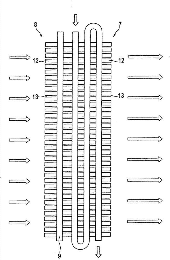
[0022] figure 1 A switchgear cabinet 1 according to the invention is shown with a switchgear interior 2 in which heat-releasing components 3 are accommodated. Adjacent to the switch cabinet 1 on the rear side in the direction of air flow (indicated by the arrows in the illustration) is a cooling device comprising a heat pipe arrangement 8 and an air-fluid heat exchanger 7 . On the front side, the switch cabinet 1 has a door element with a door panel perforated substantially over its entire height, which forms the air inlet 4 . On the vertical side 6 forming the rear side of the switch cabinet interior 2 , the air outlet 5 of the switch cabinet interior 2 is formed, which laterally overlaps the air inlet of the heat pipe arrangement 8 . The air inlet 4 and the air outlet 5 extend substantially over the entire height H of the switch cabinet interior 2 , so that an essentially horizontal air flow profile is formed in the switch cabinet interior 2 . The heat pipe arrangement 8 i...


PUM


Abstract

The invention discloses a switchgear cabinet with an arrangement for cooling off the heat from components installed in the interior of the switchgear cabinet. The arrangement comprises an air inlet which is used to introduce the air around the cabinet into the cabinet; an air outlet which is used to discharge the air in the interior of the carbinet from the vertical side surface of the interior of the cabinet, wherein the air outlet has a vertical size which is at least part of the height of the interior of the carbinet; and an air-fluid-heat exchanger, which is used to discharge hot air in the interior of the carbinet from the air outlet, wherein the air-fluid-heat exchanger at least partially extends in the vertical direction of the air outlet. The air-fluid-heat exchanger is characterized in that: at least one thermotube device of a thermotube that extends on one part of the vertical size of the air outlet is arranged between the air outlet and the air-fluid-heat exchanger in the air flow direction.

Description

technical field [0001] The invention relates to a switchgear with a device for cooling heat-releasing components accommodated in the interior of the switchgear, wherein the device has: an air inlet for the entry of ambient air into the interior of the switchgear; an air outlet for heated air from the switchgear interior to a vertical side of the switchgear interior, wherein the air outlet has such a vertical dimension that it corresponds at least to a part of the height of the switchgear interior; and has an air-fluid - A heat exchanger, via which the hot air flowing out through the air outlet is guided from the switch cabinet interior, wherein the air-fluid heat exchanger extends at least partially over the vertical dimension of the air outlet. Background technique [0002] In switchgear cabinets of the type also known, for example, from DE 10 2005 005 296 B3, the ambient air of the switchgear cabinet is usually sucked in through its vertical front side, which can be formed...

Claims


Application Information

Patent Timeline
IPC IPC(8): H02B1/56F28D15/02
CPCH05K7/20736H05K7/20818H05K7/20781
Inventor A·梅耶T·哈特曼D·贝克
Owner RITTALWERK RUDOLF LOH GMBH & CO KG
Learn More