
Intersection passage control method achieving left turning through exit lanes

A control method and intersection technology, which is applied to control traffic signals, roads, roads and other directions, can solve problems such as vehicle delays, flexible decisions, driver confusion, etc., and achieve significant effects of improving traffic capacity and alleviating traffic congestion.

Inactive Publication Date: 2014-06-18
TONGJI UNIV
View PDF13 Cites 31 Cited by
  • Summary
  • Abstract
  • Description
  • Claims
  • Application Information

AI Technical Summary

Problems solved by technology

However, this method has the following disadvantages: (1) The intersection needs to be permanently rebuilt, and it is impossible to flexibly decide whether to use this method according to actual needs; (2) It cannot solve the problem of unbalanced left-turn and straight-going flow ratios; ( 3) It cannot be used at a single entrance, and it is generally necessary to adopt this design method for two opposite entrances; (4) The distance between intersections needs to meet the requirements of two queuing lengths and lane changes
However, this method has the following disadvantages: (1) For unsaturated conditions, it may cause an increase in the average vehicle delay, so it is generally only applicable to oversaturated conditions; (2) The distance between intersections needs to meet two queue lengths and lanes (3) Although there is no need to carry out civil engineering transformation on the intersection, theoretically it can be flexibly decided whether to adopt this method, but when this method is not adopted, the lane function of the intersection can only be prompted by variable signs, It cannot be determined by ground markings, which may cause driver confusion, so it does not have good flexibility to enable or disable in actual operation

Method used


Image

  • Intersection passage control method achieving left turning through exit lanes
  • Intersection passage control method achieving left turning through exit lanes
  • Intersection passage control method achieving left turning through exit lanes

Examples


Embodiment 1

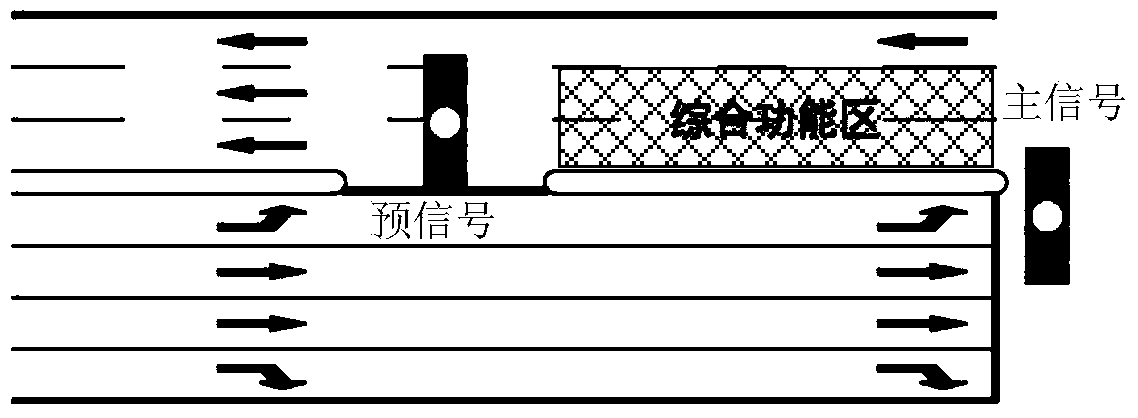
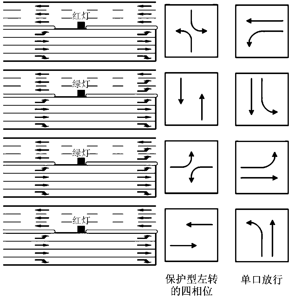
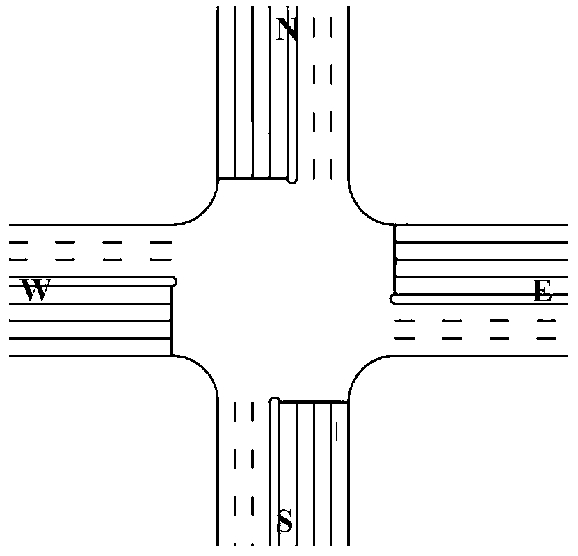
[0056] Such as image 3 and as shown in Table 1, figure 1 It is a schematic diagram of the geometric conditions of the intersection in the embodiment of the present invention, which is a cross intersection, and the entrance and exit roads of each fork are respectively 4 lanes and 3 lanes; Table 1 is the traffic demand of the intersection in the embodiment of the invention. The saturated flow rate is 1800(pcu / h / ln), the value range of the signal period is [60,120](s), the green light interval between each phase is 3(s), and the total signal loss time is 12(s), the vehicle The minimum passing speed is 10(m / s); the safety time interval is 4(s). Adopt the method among the present invention now to the west entrance of the intersection, be the goal by the maximum of the reserve traffic capacity of the intersection, and based on the signal phase of parallel double-ring concept (dual-ring concurrent) (such as Figure 4 As shown, a protective left-turn phase design method that allows...


PUM


Abstract

Provided is an intersection passage control method achieving left turning through exit lanes. For an intersection controlled by signals, on the basis of the traditional intersection geometric space design and the signal control design, space and time resources of the intersection are further optimized, all or part of the exist lanes are used as left turning lanes at a certain stage of the signal cycle, and additional right of way is provided for left turning traffic. The intersection passage control method particularly comprises the two steps of intersection space arrangement and signal control, wherein the space arrangement step comprises arrangement of a comprehensive functional area and a central lane separator opening, and setting of a pre-signal and a parking line; the signal control step comprises intersection main signal phase and phase sequence setting, intersection main signal timing setting and pre-signal timing setting. The method can provide the additional right of way for the left turning traffic, thereby improving the passage capacity of the intersection, reducing car average delay and solving or relieving traffic jam.

Description

technical field [0001] The invention belongs to the fields of traffic engineering and traffic information and control systems, and relates to the technical fields of lane layout and signal phase design at intersections, and more specifically, relates to a traffic control method at an intersection that uses an exit road to realize a left turn. Background technique [0002] Level intersections are the bottleneck nodes of urban road traffic. How to optimize the space-time resources of intersections is the key to improving the operation efficiency of intersections. However, the current research discusses on the premise of dividing the intersections into entrance lanes and exit lanes, and mainly focuses on the lane function division and signal control of the intersection entrance lanes. Research on improving the utilization efficiency of outlets, and no invention patents for such methods have been retrieved. [0003] According to the literature search of the prior art, it is fou...

Claims


Application Information

Patent Timeline
Patent Type & Authority Applications(China)
IPC IPC(8): G08G1/07E01C1/02
Inventor 马万经赵靖杨晓光
Owner TONGJI UNIV
Learn More