
Cone plate type stepless speed changer

A continuously variable transmission, cone-disc type technology, applied to components with teeth, belts/chains/gears, mechanical equipment, etc., can solve problems such as insufficient compact structure, inability to transmit torque in reverse, and large axial size of the transmission , to achieve compact structure, reduce system load and improve efficiency

Active Publication Date: 2014-06-18
CHANGZHOU DONGFENG CVT
View PDF9 Cites 34 Cited by
  • Summary
  • Abstract
  • Description
  • Claims
  • Application Information

AI Technical Summary

Problems solved by technology

However, this continuously variable transmission also has defects and deficiencies. First, the speed regulating mechanism and the pressurizing mechanism are installed on the same movable cone, and the pressurizing part needs to meet the axial movement stroke of the movable cone speed regulation at the same time, resulting in the speed of the transmission. The axial size is large and the structure is not compact enough; second, the pressurization mechanism can only pressurize in one direction and cannot transmit torque in the opposite direction, so it can only be used in the case of one-way transmission of motion and torque

Method used


Image

  • Cone plate type stepless speed changer
  • Cone plate type stepless speed changer
  • Cone plate type stepless speed changer

Examples


Embodiment Construction

[0038] The present invention will be further described below in conjunction with the accompanying drawings and embodiments.

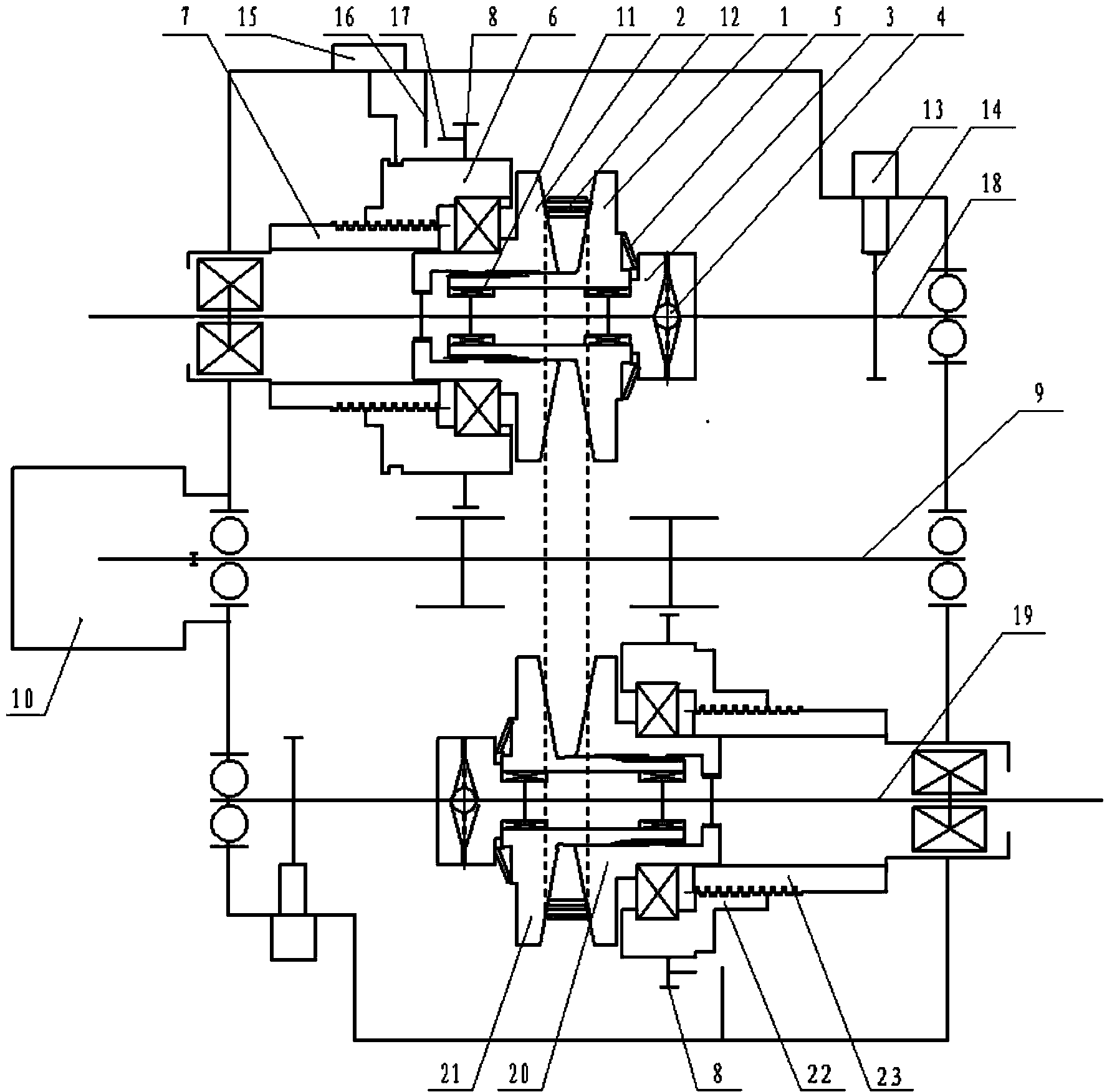
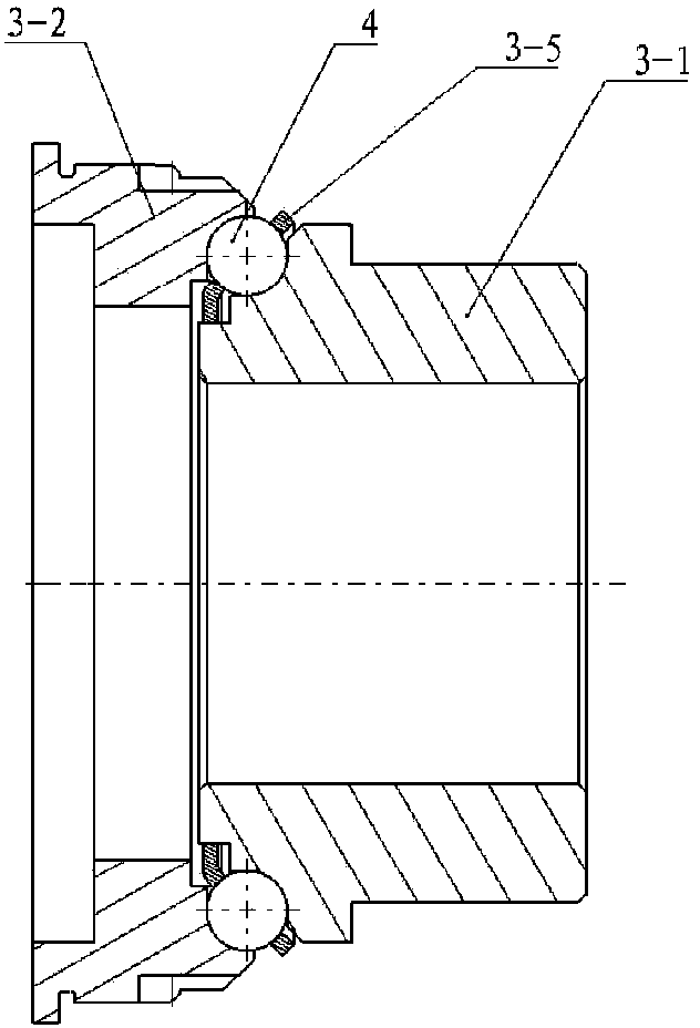
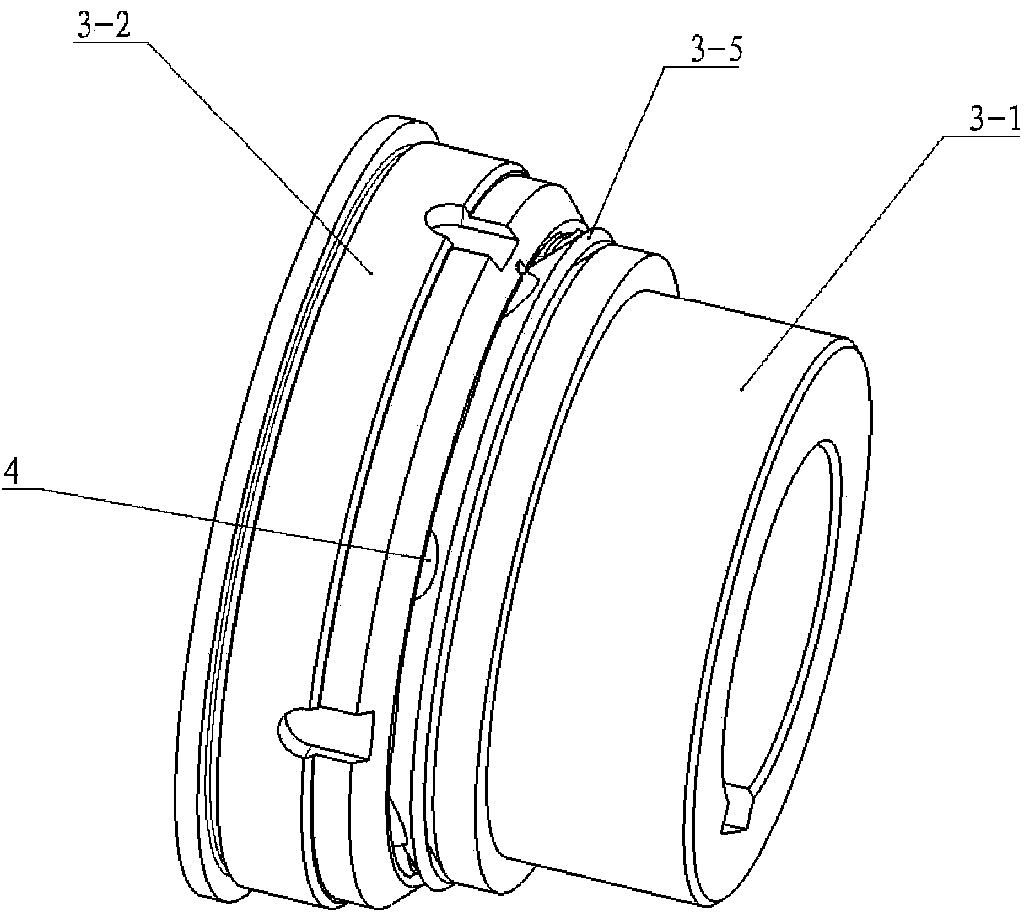
[0039] combine figure 1 , the cone-disk type continuously variable transmission of the present invention is installed on the drive shaft 18 by the drive shaft moving cone 2 and the drive shaft pressurized cone 1. The driven cone is composed of the driven shaft driven cone 20 and the driven shaft pressurized cone 21, the active cone and the driven cone clamp the flexible transmission element 12, and the flexible transmission element can adopt a continuously variable transmission Use a thrust steel belt, or a metal belt, or a chain, or a V-belt. The pressure cone of the driving shaft and the pressure cone of the driven shaft respectively maintain a connection relationship with the driving shaft 18 and the driven shaft 19 through the needle bearing 11, which can move within 1 mm on the transmission shaft but cannot rotate with each other; The shaft movin...


PUM


Abstract

The invention provides a cone plate type stepless speed changer. A driving cone plate and a driven cone plate respectively consist of a pair of movable cone plates and pressurizing cone plates, a pressurizing mechanism consists of an end surface cam pressurizing mechanism arranged at the back side of at least one pressurizing cone plate in a driving shaft pressurizing cone plate and a driven shaft pressurizing cone plate, a speed regulating mechanism consists of a speed reducing shaft, a hollow screw rod and a screw nut, the hollow screw rod and the screw nut are respectively arranged at the back side of a driving shaft movable cone plate and a driven shaft movable cone plate, the hollow screw rod and the screw nut are of ball screw structures or sliding spiral structures, through a speed regulating shaft and a constant ratio transmission mechanism, the conversion relationship of the rotation of the speed regulating shaft to the axial movement of the driving shaft movable cone plate and the driven shaft movable cone plate meets a formula that i1=i2, and the driving shaft movable cone plate and the driven shaft movable cone plate are enabled to do synchronous identical-speed and identical-direction movement. The end surface cam pressurizing mechanism and the speed regulating mechanism of the speed changer are separated in space, the axial dimension of the pressurizing mechanism can be reduced, the positive and reverse two-way pressurization can be realized through the end surface cam pressurizing mechanism, the pressurizing pressure can be regulated in real time along with the transmission torque, the transmission efficiency is high, the service life of a system is long, and the reliability is high.

Description

technical field [0001] The invention relates to a transmission, in particular to a cone-disk type continuously variable transmission. Background technique [0002] Cone-disk continuously variable transmissions transmit power and movement by means of friction through flexible transmission components clamped between the cone discs, such as rubber belts, steel belts, chains, etc., and are widely used in vehicles, construction machinery and other power machinery . The pressure system and speed regulation system of the cone-disk continuously variable transmission are the key parts of the continuously variable transmission. The friction transmission between the cone disk and the flexible transmission assembly is realized through the pressure system, and the speed change function is realized through the speed regulation system. [0003] Since the advent of continuously variable transmissions, its technical development has always been aimed at the pursuit of transmission efficiency...

Claims


Application Information

Patent Timeline
Patent Type & Authority Applications(China)
IPC IPC(8): F16H37/00F16H25/20
CPCF16H9/18F16H61/66272F16H2061/6604
Inventor 程乃士
Owner CHANGZHOU DONGFENG CVT
Learn More