
Retarder cooling system

A technology of cooling system and retarder, which is applied in the direction of engine cooling, machine/engine, engine components, etc. It can solve the problems of low engine water temperature, unfavorable engine energy saving and emission reduction, and lower engine operating temperature.

Active Publication Date: 2014-06-18
DONGFENG FUJI THOMSON THERMOSTAT
View PDF6 Cites 9 Cited by
  • Summary
  • Abstract
  • Description
  • Claims
  • Application Information

AI Technical Summary

Problems solved by technology

In this way, due to the setting of 76 degrees, the engine water temperature will be too low during non-long downhill, resulting in increased fuel consumption and worsened emissions
The disadvantages of the existing retarder thermostat scheme, in addition to the lowering of the engine operating temperature, is not conducive to the energy saving and emission reduction of the engine; in addition, due to the poor sensitivity of the traditional wax-type thermostat, when the retarder intervenes, it cannot Rapidly increasing the flow rate of the large cycle, the retarder has to take measures to limit the braking torque to adapt to the sensitivity of the thermostat, thus limiting the function of the retarder at the initial stage of braking

Method used


Image

  • Retarder cooling system
  • Retarder cooling system
  • Retarder cooling system

Examples


Embodiment

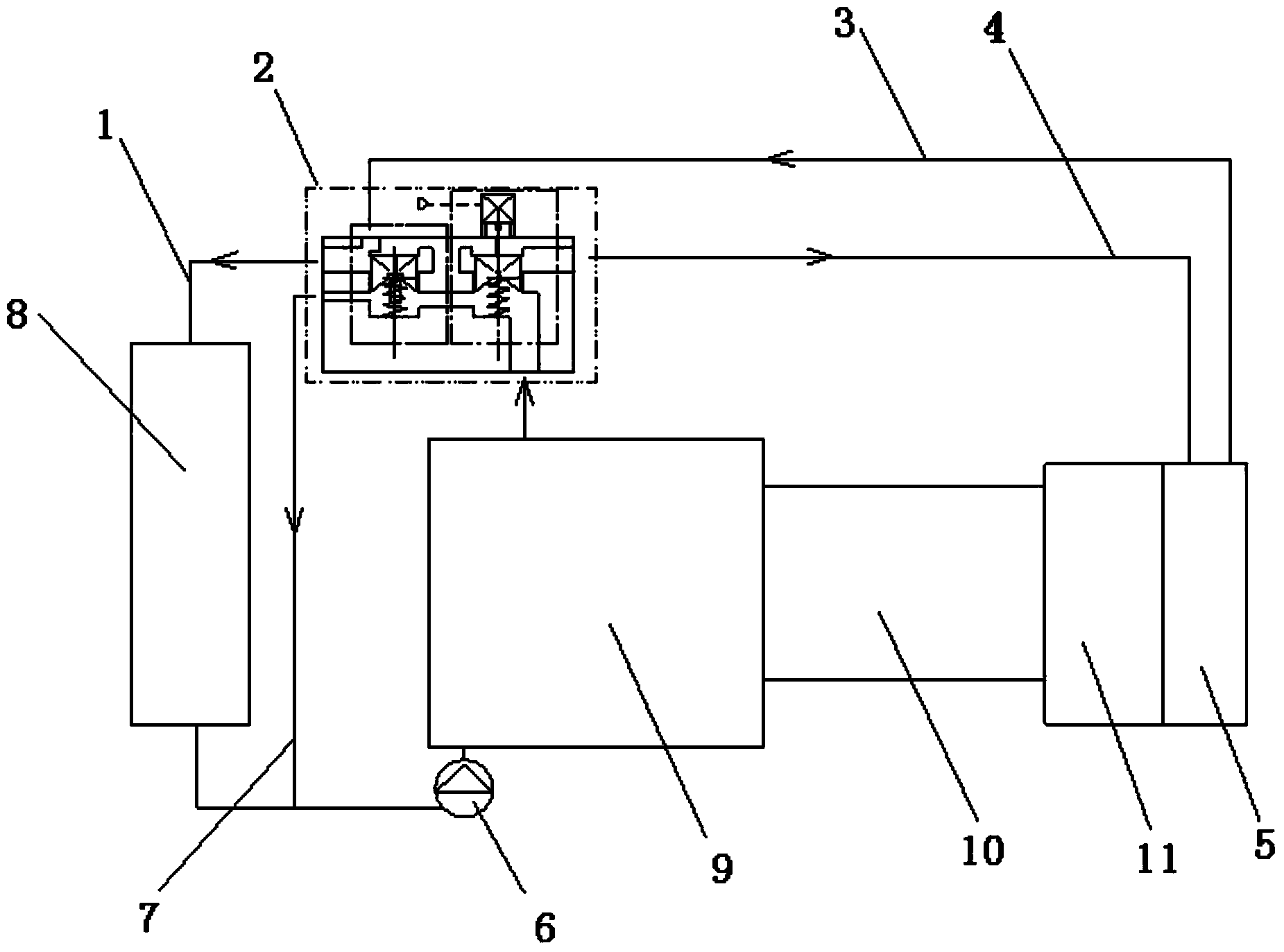
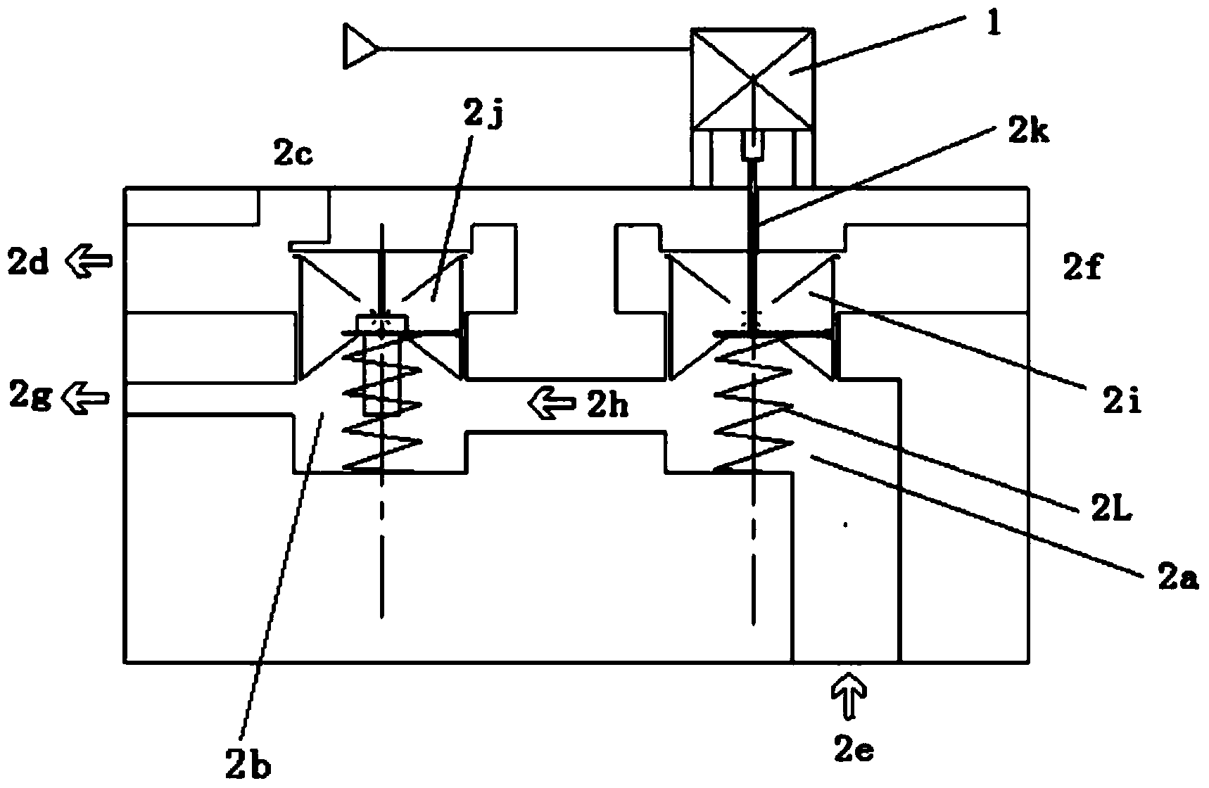
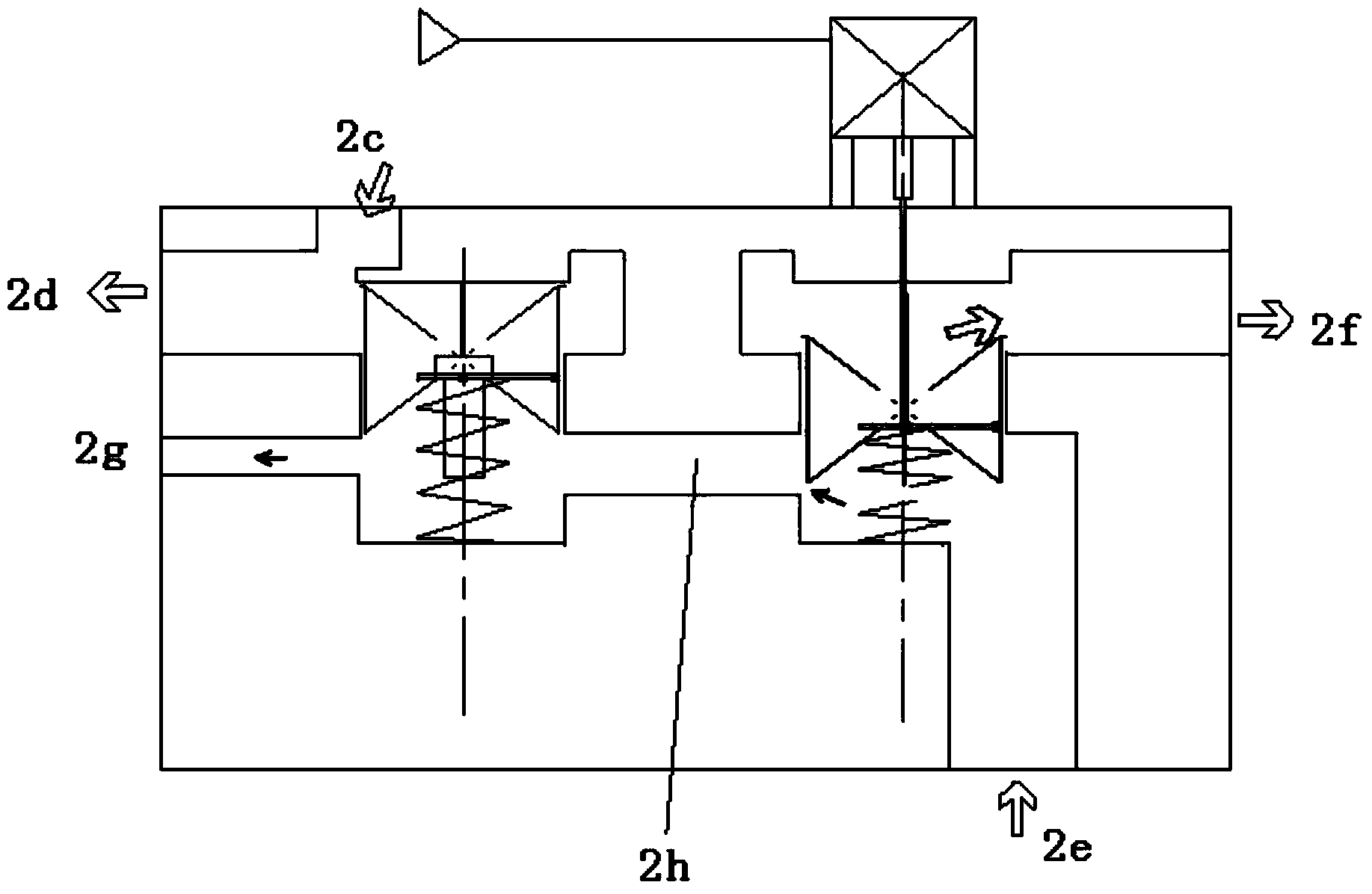
[0010] Embodiment: The present invention comprises radiator 8, engine 9, transmission 10, water pump 6, retarder 11 and heat exchanger 5, and engine 9, transmission 10, retarder 11 and heat exchanger 5 are connected in sequence. It also includes a thermostat 2 provided with a first cavity 2a and a second cavity 2b, the first cavity 2a is provided with a cooling water inlet 2e and a cooling water outlet 2f, the second cavity 2b is provided with a hot water inlet 2c, a large circulation interface 2d and a small circulation interface 2g, the first cavity 2a and the second cavity 2b are connected through a connecting pipe 2h, and the first cavity 2a is equipped with There is a first valve 2i used to control the opening and closing of the connecting pipe 2h and the cooling water outlet 2f. The second cavity 2b is provided with a second valve 2j for controlling the opening and closing of the hot water inlet 2c and the small circulation interface 2g. The water outlet of the engine 9 ...


PUM


Abstract

The invention discloses a retarder cooling system. The retarder cooling system comprises a radiator, an engine, a transmission, a water pump, a retarder, a heat exchanger and a temperature regulator with a first chamber and a second chamber, the first chamber is provided with a cooling water inlet and a cooling water outlet, the second chamber is provided with a hot water inlet, a big circulation port and a small circulation port, the first chamber is communicated with the second chamber through a connecting tube, and a first valve for controlling the opening or closing of the connecting tube and the like are arranged in the first chamber. Not only is the structure of the retarder cooling system simple and small, but also the action of the retarder cooling system is linked with the retarder, and thereby the retarder can be rapidly cooled.

Description

technical field [0001] The invention relates to the technical field of retarder cooling, in particular to a retarder cooling system. Background technique [0002] The hydraulic retarder is activated by the operating handle. During the working period, the heating power is as high as 200-600 kilowatts. It needs to dissipate heat quickly. The oil temperature should be controlled below 160 degrees to avoid oil deterioration. The main route of its traditional cooling cycle is: engine water outlet - retarder heat exchanger - thermostat - large circulation (radiator) / small circulation - water pump - engine water inlet, the core of this scheme is The traditional wax-type thermostat connects the engine cooling system with the main channel of the retarder heat exchanger. In order to prevent the oil overheating problem of the retarder, that is, to solve the problem of rapid heat dissipation of the retarder, while increasing the flow rate of the thermostat, the initial opening temper...

Claims


Application Information

Patent Timeline
IPC IPC(8): F01P11/00
Inventor 王乾吴晓飞
Owner DONGFENG FUJI THOMSON THERMOSTAT
Learn More