
Mixer system

A mixer system and mixer technology, which are applied in the directions of machines/engines, mufflers, engine components, etc., can solve the problems that the injector cannot accurately realize the function and reduce the efficiency of the mixer.

Inactive Publication Date: 2014-06-18
FORD OTOMOTIV SANAYI ANONIM SIRKETI
View PDF6 Cites 0 Cited by
  • Summary
  • Abstract
  • Description
  • Claims
  • Application Information

AI Technical Summary

Problems solved by technology

[0003] During this reduction, the exhaust gas, after hitting the injection particles, accumulates in the chamber where the injection is performed towards the chamber and this prevents the injector from performing its function exactly
At the same time, the injected particles do not reach the mixer uniformly with the exhaust gas distribution, which reduces the efficiency of the mixer to fulfill its function

Method used


Image

  • Mixer system
  • Mixer system
  • Mixer system

Examples


Embodiment Construction

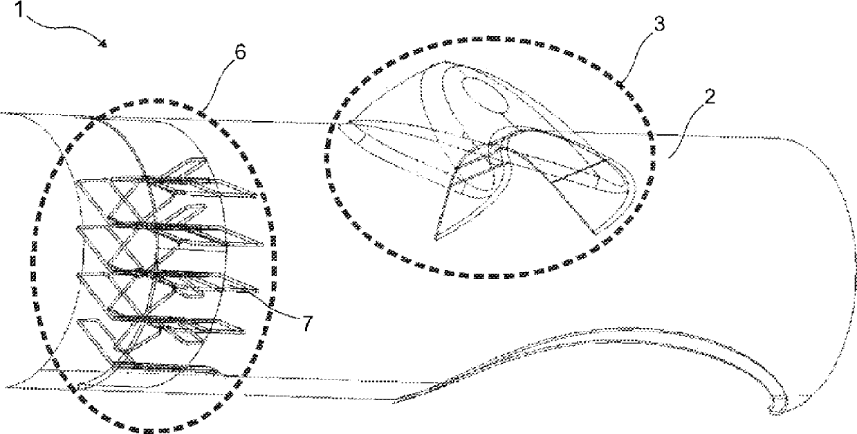
[0020] A mixer system 1 for controlling the behavior of gases injected into the exhaust gas in the exhaust gas, the mixer system basically comprising:

[0021] - at least one exhaust body 2 through which the gases emitted by the fuel burned in the engine of the vehicle are transferred to the external environment,

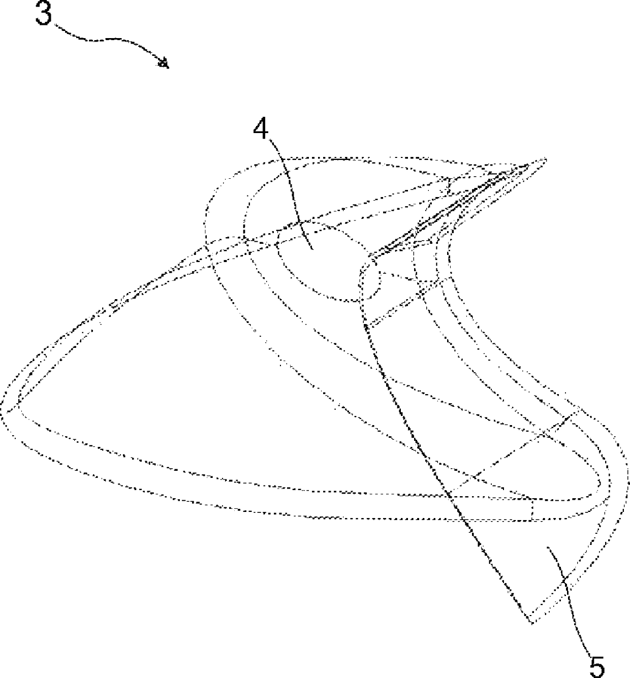
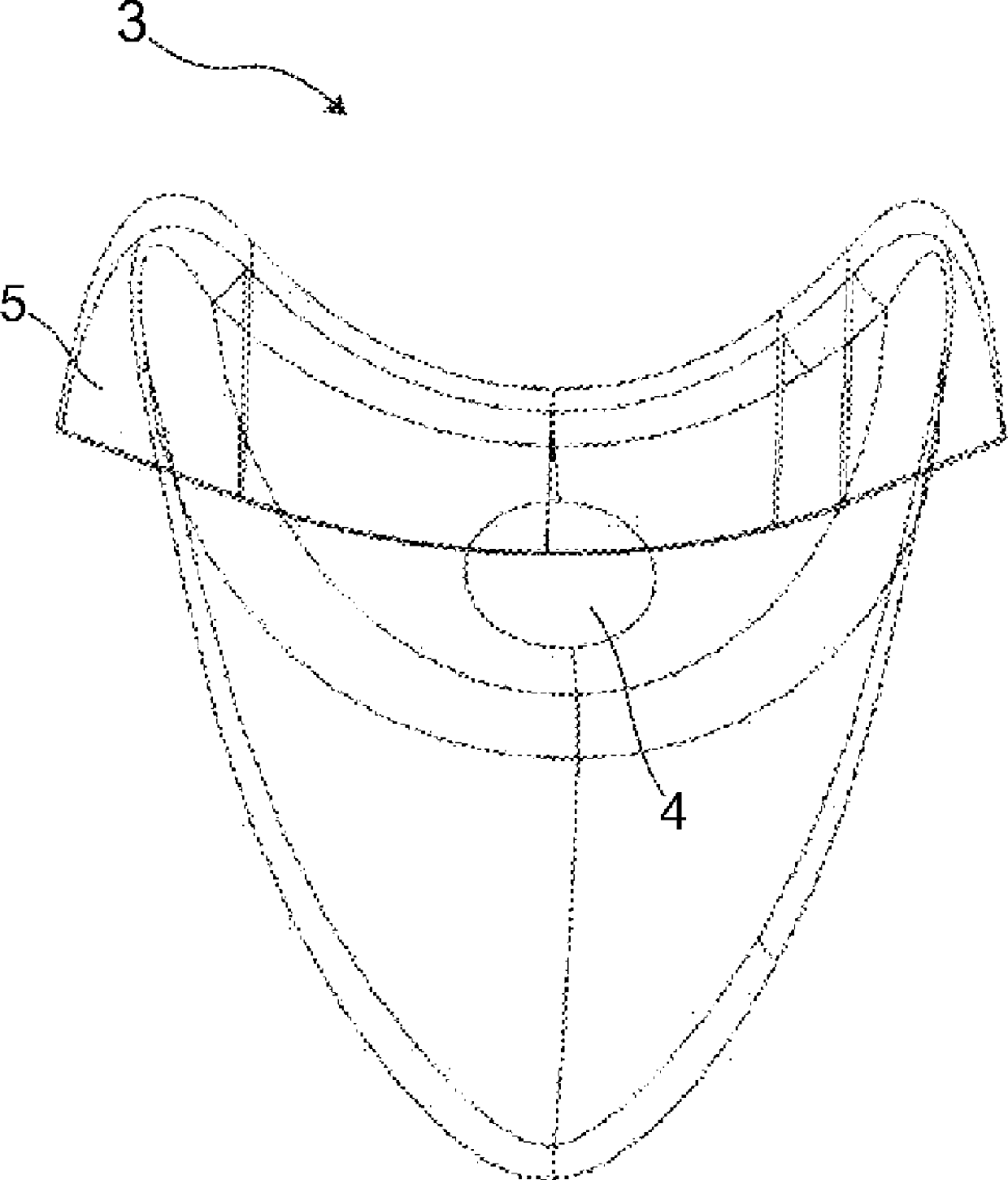
[0022] - at least one injector 3, which is mounted on the exhaust body 2 and makes it possible to reduce the emission of exhaust gases,

[0023] - at least one nozzle 4 enabling the injection of emission-reducing particles to the exhaust body 2,

[0024] - at least one fin 5 enabling the abatement particles leaving the nozzle 4 to be directed in a preferred direction,

[0025] - at least one mixer 6 which enables efficient mixing of the abatement particles injected by the injector 3 with the exhaust fume,

[0026] - At least one baffle 7 which is located in the mixer 6 and which enables the mixture of abatement particles and exhaust smoke to advance in a preferred...


PUM


Abstract

The invention relates to a mixer system which controls the behavior of gas injected to the exhaust in the exhaust and comprises at least one injector (3) which is mounted onto an exhaust main body (2) and enables reduction in exhaust emissions; at least one mixer (6) which allows the emission particles injected by the injector (3) to be mixed efficiently with exhaust smoke.

Description

technical field [0001] The present invention relates to a mixer system that controls the behavior of gases injected into the exhaust gas within the exhaust gas. Background technique [0002] When emission standards were accepted, emission limits that had been reduced to lower levels required the use of advanced exhaust systems. The lowering of this particulate emission limit and the reduction of NOx emissions both require devices such as Selective Catalytic Reduction (SCR) and Diesel Oxidation Catalysts (DOC) in the exhaust system. In order for the catalyst to perform a surface reaction, various fluids such as fuel or urea should be injected into the system. The behavior of the reducing gas injected within the system plays a key role in exceeding emission limits. [0003] During this reduction, the exhaust gas, after striking the injection particles, accumulates in the chamber towards which the injection is performed, and this prevents the injector from performing its func...

Claims


Application Information

Patent Timeline
Patent Type & Authority Applications(China)
IPC IPC(8): F01N3/20F01N3/10
Inventor S.埃伦古拉O.厄斯I.H.萨维斯
Owner FORD OTOMOTIV SANAYI ANONIM SIRKETI
Learn More