Horizontal type machine tool automatic clamping device and horizontal type machine tool

An automatic clamping, horizontal technology, applied in the direction of clamping device, positioning device, clamping, etc., can solve the problems of increasing enterprise cost, prolonging processing time, reducing enterprise efficiency, etc., to reduce work intensity, increase enterprise efficiency, The effect of reducing business costs

Inactive Publication Date: 2014-06-18
重庆雁山机械制造(集团)有限公司
View PDF6 Cites 10 Cited by
  • Summary
  • Abstract
  • Description
  • Claims
  • Application Information

AI Technical Summary

Problems solved by technology

[0003] In the prior art, see figure 1 , figure 1 It is a schematic diagram of the structure of the clamping device of the horizontal machine tool before press-fitting in the prior art. The clamping device of the horizontal machine tool usually clamps the shaft parts 4 in the way of one clamp and one top, including the chuck 3, the opposite The indexing head 2 and tailstock 6 arranged on the workbench 1 of the horizontal machine tool, the collet 3 is a manual chuck, and is arranged on the indexing head 2 towards the side of the tailstock 6, and the tailstock 6 is provided with The handle 7 is used to extend or retract the tip 5 by hand. When installing the shaft part 4, it is necessary to manually rotate the chuck 3 to clamp one end of the shaft part 4, and then shake the handle 7 to make the tip 5 stretches out until the tip 5 bears against the other end of the shaft part 4. After finishing the processing, it is necessary to shake the handle 7 first to withdraw the tip 5, and then rotate the manual chuck 3 in the opposite direction to let go of the shaft part 4. This clamp Tight way, slow speed, low efficiency, high work intensity, prolonging the processing time, increasing the cost of the enterprise and reducing the benefit of the enterprise

Method used


Image

  • Horizontal type machine tool automatic clamping device and horizontal type machine tool
  • Horizontal type machine tool automatic clamping device and horizontal type machine tool

Examples


Embodiment Construction

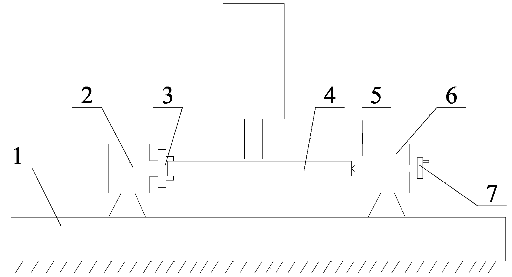
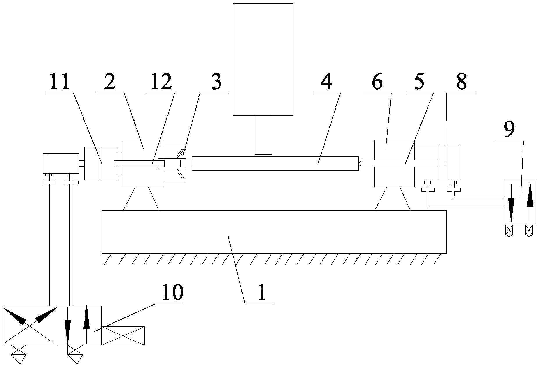
[0023] The invention provides an automatic clamping device for a horizontal machine tool and a horizontal machine tool, so that after the automatic clamping device for a horizontal machine tool is used in a horizontal machine tool, the clamping speed of shaft parts can be increased, and the working intensity can be reduced. The purpose of shortening the processing time, reducing the cost of the enterprise and increasing the benefit of the enterprise.

[0024] The following will clearly and completely describe the technical solutions in the embodiments of the present invention with reference to the accompanying drawings in the embodiments of the present invention. Obviously, the described embodiments are only some, not all, embodiments of the present invention. Based on the embodiments of the present invention, all other embodiments obtained by persons of ordinary skill in the art without making creative efforts belong to the protection scope of the present invention.

[0025] ...


PUM


Abstract

The invention discloses a horizontal type machine tool automatic clamping device. A chuck is a spring chuck, a first through hole is formed in an indexing head, an opening of the end, facing a tail base, of the first through hole is gradually expanded from inside to outside, the opening is matched with the outer side wall of the chuck, a first piston cylinder is arranged on the side, deviating from the tail base, of the indexing head, a pull rod is connected to a first piston rod of the first piston cylinder, the pull rod penetrates through the first through hole and is connected with the chuck, a second through hole coaxial with the first through hole is formed in the tail base, a second piston cylinder is arranged on the side, deviating from the indexing head, of the tail base, a tip is connected with a second piston rod of the second piston cylinder, and the second piston rod is used for driving the tip to stretch out of or retract to the second through hole. A shaft part is clamped through switches of the two piston cylinders, and compared with an existing clamping mode, the speed is high, efficiency is high, the operation is easy, work intensity is lowered, machining time is shortened, then enterprise cost is lowered, and enterprise benefits are improved. The invention further discloses a horizontal type machine tool.

Description

technical field [0001] The invention relates to the technical field of mechanical processing, in particular to an automatic clamping device for a horizontal machine tool and a horizontal machine tool. Background technique [0002] When using a horizontal machine tool to process shaft parts, in order to ensure that the shaft parts stay firmly in the processing position and avoid the shaft parts from flying out, affecting production, and even causing injury to the staff, it is necessary to set clamps on the horizontal machine tool. Clamping device for clamping shaft parts. [0003] In the prior art, see figure 1 , figure 1 It is a schematic diagram of the structure of the clamping device of the horizontal machine tool before press-fitting in the prior art. The clamping device of the horizontal machine tool usually clamps the shaft parts 4 in the way of one clamp and one top, including the chuck 3, the opposite The indexing head 2 and tailstock 6 arranged on the workbench 1 ...

Claims


Application Information

Patent Timeline
IPC IPC(8): B23Q3/08B23B23/00
CPCB23Q3/08B23Q2703/04
Inventor 黄官富
Owner 重庆雁山机械制造(集团)有限公司
Why Eureka
Try Eureka