
an escape device

An escape device and speed drop technology, which is applied in the field of escape devices, can solve the problems of the escaper adjusting the speed reduction, threatening the life of the escapee, and the speed reduction is too fast, etc., so as to improve safety protection measures, facilitate carrying and transferring, and have a reasonable structural design Effect

Inactive Publication Date: 2017-02-08
SHENZHEN MUNICIPAL DESIGN & RES INST
View PDF6 Cites 1 Cited by
  • Summary
  • Abstract
  • Description
  • Claims
  • Application Information

AI Technical Summary

Problems solved by technology

[0004] 1. Existing escape equipment only has movable pulleys or fixed pulleys for single-strand ropes to descend and slide. The escapers cannot control the speed of their descent, which poses a great risk to the escapers and increases the fear of the escapers;
[0005] 2. Although the existing escape equipment is designed with a descending adjustment device, it cannot automatically adjust the deceleration according to the weight of different escapees, and it is easy for a heavy escaper to decelerate too fast and threaten the life of the escapee;
[0006] 3. The existing escape equipment is not designed with an emergency braking device. If the escape equipment fails, the life of the escapee cannot be protected;
[0007] 4. Existing escape equipment is even designed to use electricity as power. When a fire occurs, the power supply is cut off, and the escape equipment cannot be used at all.
[0008] In addition, in these building escape equipment, the ropes used for the rapid descent and the damping materials used to control the descent are mostly traditional steel materials, which are heavy and are not conducive to wearing and transferring.

Method used


Image

  • an escape device
  • an escape device
  • an escape device

Examples


other Embodiment approach

[0074] In other embodiments, the escape device can also be pre-installed in the invisible inner wall firmware according to the structural characteristics of the building, and the safety waist belt can be installed when in use.

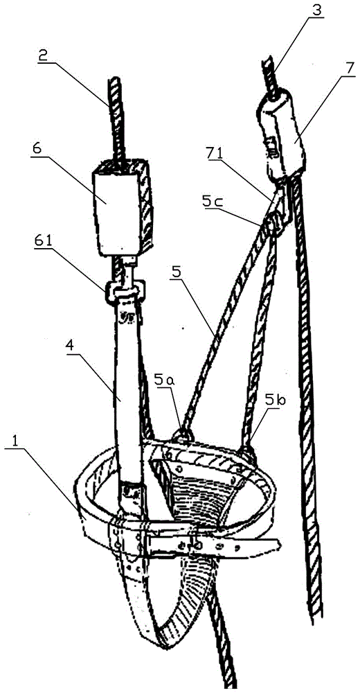
[0075] Implementing the escape device of the present invention has the following beneficial effects, because one end of the connector is connected to the safety waist belt, and the other end is connected to the main rope for rapid descent through the single speed limiting box; the Kevlar fiber connection rope One end is connected to the safety waist belt, and the other end is connected to the rapid descent escape auxiliary rope through the damping adjuster. The deceleration can be automatically adjusted according to the weight of the escapee to prevent the life-threatening situation caused by the excessive weight of the escapee and the rapid deceleration; it is equipped with an emergency braking function, which improves the safety protection measures an...


PUM


Abstract

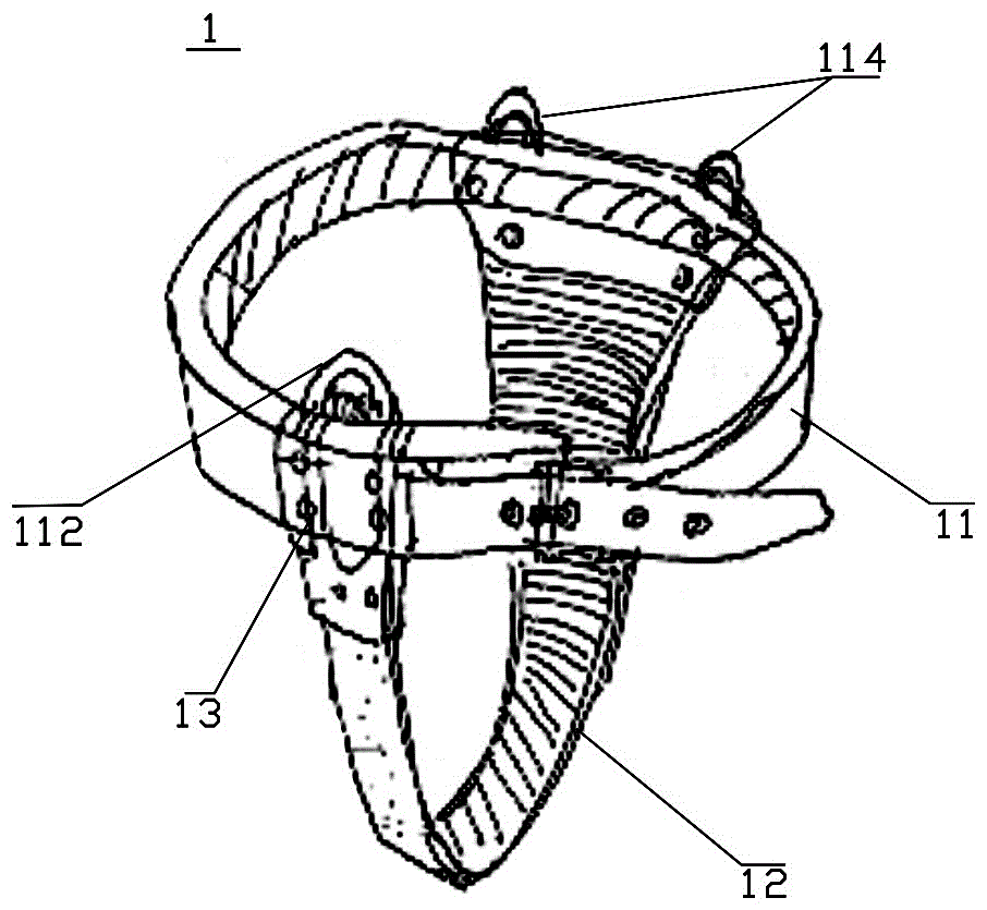
The invention discloses an escape device which at least comprises a safety waist and trouser belt, a prompt drop escape main rope, a prompt drop escape auxiliary rope, a connector, a Kevlar fiber connecting rope, a single speed-limiting box and a damper regulator, wherein the single speed-limiting box is connected onto the prompt drop escape main rope and used for dropping at a constant speed relative to the prompt drop escape main rope, the damper regulator is connected onto the prompt drop escape auxiliary rope and used for controlling the drop speed, one end of the connector is connected onto the safety waist and trouser belt, the other end of the connector is connected onto the prompt drop escape main rope through the single speed-limiting box, one end of the Kevlar fiber connecting rope is connected onto the safety waist and trouser belt, and the other end of the Kevlar fiber connecting rope is connected onto the prompt drop escape auxiliary rope through the damper regulator. Based on improvement of safety protection measures, the drop speed can be automatically regulated according to the weight of an escaper, the ropes are high in strength, fine in abrasion resistance, light in weight and beneficial to carrying and transfer, and the escape device is reasonable in structural design and simple, convenient and rapid to use.

Description

technical field [0001] The invention relates to the field of machinery, in particular to an escape device for safe and rapid escape of trapped persons. Background technique [0002] With the development of social economy, there are more and more high-rise buildings in cities, and the safety crisis of high-rise fires or sudden natural disasters are gradually highlighted. A fire in a high-rise teacher's apartment in Shanghai caused many residents to die in the sea of ​​flames, which sounded the alarm for the fire safety of high-rise buildings in the city. It also made the elevator unusable and the corridors and stairs blocked by smoke in the event of a fire and other emergencies. How to safely and quickly escape the trapped people has become an urgent problem to be solved. [0003] There have been a large number of reports related to building escape equipment in China, and patented technologies related to high-rise building escape equipment have also emerged. In these disclos...

Claims


Application Information

Patent Timeline
Patent Type & Authority Patents(China)
IPC IPC(8): A62B1/10
Inventor 陈宜言谢云飞陈奋
Owner SHENZHEN MUNICIPAL DESIGN & RES INST
Learn More