
Electric level converter

A level converter and transistor technology, applied in the direction of logic circuit connection/interface layout, etc., can solve the problems of area loss, increase the size of M3 and M4 tubes, etc., and achieve the effect of reducing area and improving flipping speed

Inactive Publication Date: 2014-06-11
SHANGHAI HUAHONG GRACE SEMICON MFG CORP
View PDF5 Cites 3 Cited by
  • Summary
  • Abstract
  • Description
  • Claims
  • Application Information

AI Technical Summary

Problems solved by technology

The disadvantage is that in order to ensure the normal flipping and flipping speed of the level, the size of the M3 and M4 tubes will be increased, resulting in area loss

Method used


Image

  • Electric level converter
  • Electric level converter
  • Electric level converter

Examples


Embodiment Construction

[0015] In order to enable your examiners to have a further understanding and understanding of the purpose, features and effects of the present invention, the following detailed description is as follows with the accompanying drawings.

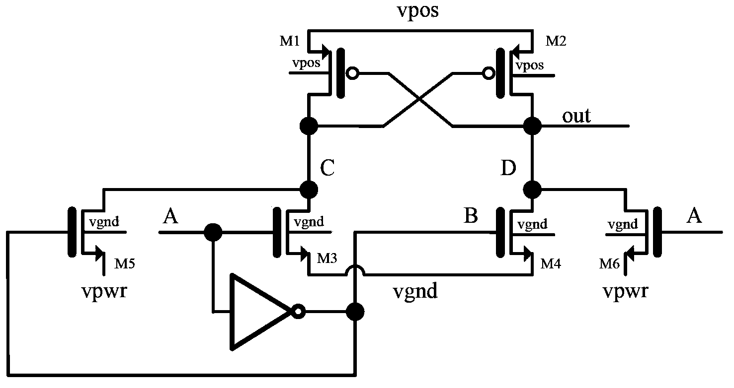
[0016] Such as figure 2 As shown, the source terminals of the first transistor M1 and the second transistor M2 are connected to the external high voltage power supply (vpos), the drain of the first transistor M1, the gate of the second transistor M2, the drain of the third transistor M3 and The drain of the fifth transistor M5 is connected to point C, the gate of the first transistor M1, the drain of the second transistor M2, the drain of the fourth transistor M4 and the drain of the sixth transistor M6 are connected to point D, and serve as The circuit output terminal (out), the gate of the third transistor M3, the gate of the sixth transistor M6 are connected to the input terminal of the inverter at point A, the output terminal of the invert...


PUM


Abstract

This invention discloses an electric level converter. Source electrodes of a first transistor and a second transistor are connected to an external high-voltage power supply; the drain electrode of the first transistor, the grid electrode of the second transistor, the drain electrode of a third transistor and the drain electrode of a fifth transistor are connected, the grid electrode of the first transistor and the drain electrodes of the second transistor, a fourth transistor and the sixth transistor are connected and are used as an output terminal of the circuit, the grid electrodes of the third transistor and the sixth transistor are connected to the input terminal of an inverter, the output terminal of the inverter is connected to the grid electrodes of the fourth transistor and the fifth transistor, the source electrodes of the third transistor and the fourth transistor are connected to the ground, and the source electrodes of the fifth transistor and the sixth transistor are connected and connected to the voltage of the external power supply. The electric level converter not only improves the inverting efficiency of the voltage, but also reduces the area of the circuit board.

Description

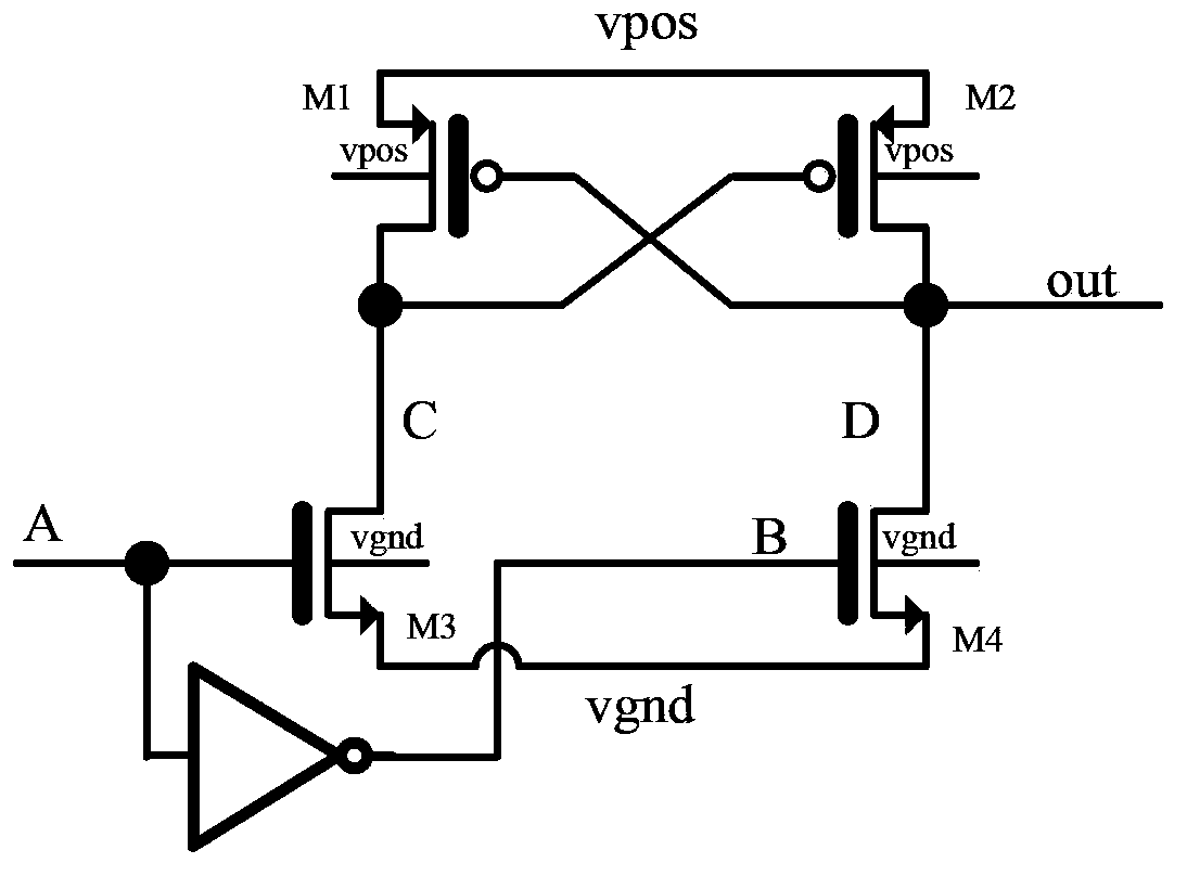
technical field [0001] The invention relates to the field of semiconductor integrated circuit manufacturing, in particular to a level shifter. Background technique [0002] The level shifter (Level shifter) mainly realizes the conversion of the voltage domain through the digital signal, and outputs voltages in different ranges. When converting and outputting positive high voltage, the traditional method is to use nhv (high-voltage n-type transistor) as a pull-down transistor, which is directly connected to the drain of the upper phv (high-voltage p-type transistor). Such as figure 1 As shown, the source terminals of transistor M1 and transistor M2 are connected to vpos (external high voltage power supply), the drain of transistor M1, the gate of transistor M2 and the drain of transistor M3 are connected to point C, the gate of transistor M1, The drain of the transistor M2 and the drain of the transistor M4 are connected to the D point, and as the circuit output (out), the ...

Claims


Application Information

Patent Timeline
Patent Type & Authority Applications(China)
IPC IPC(8): H03K19/0175
Inventor 王鑫冯国友
Owner SHANGHAI HUAHONG GRACE SEMICON MFG CORP
Learn More