
Non-salient pole electromagnetic speed regulator

An electromagnetic speed regulation, hidden pole technology, applied in electrical components, electromechanical devices, magnetic circuit rotating parts, etc. Wide range, low cost, and the effect of reducing current inrush

Inactive Publication Date: 2014-06-11
杨玉岗
View PDF8 Cites 1 Cited by
  • Summary
  • Abstract
  • Description
  • Claims
  • Application Information

AI Technical Summary

Problems solved by technology

But it also has disadvantages: first, the permanent magnet is small in size, the torque generated is small, and the speed regulation range is limited; second, the permanent magnet will be demagnetized or even demagnetized when it is heated and operated for a long time; third, the mechanical device structure for adjusting the air gap complex

Method used


Image

  • Non-salient pole electromagnetic speed regulator
  • Non-salient pole electromagnetic speed regulator
  • Non-salient pole electromagnetic speed regulator

Examples


Embodiment 1

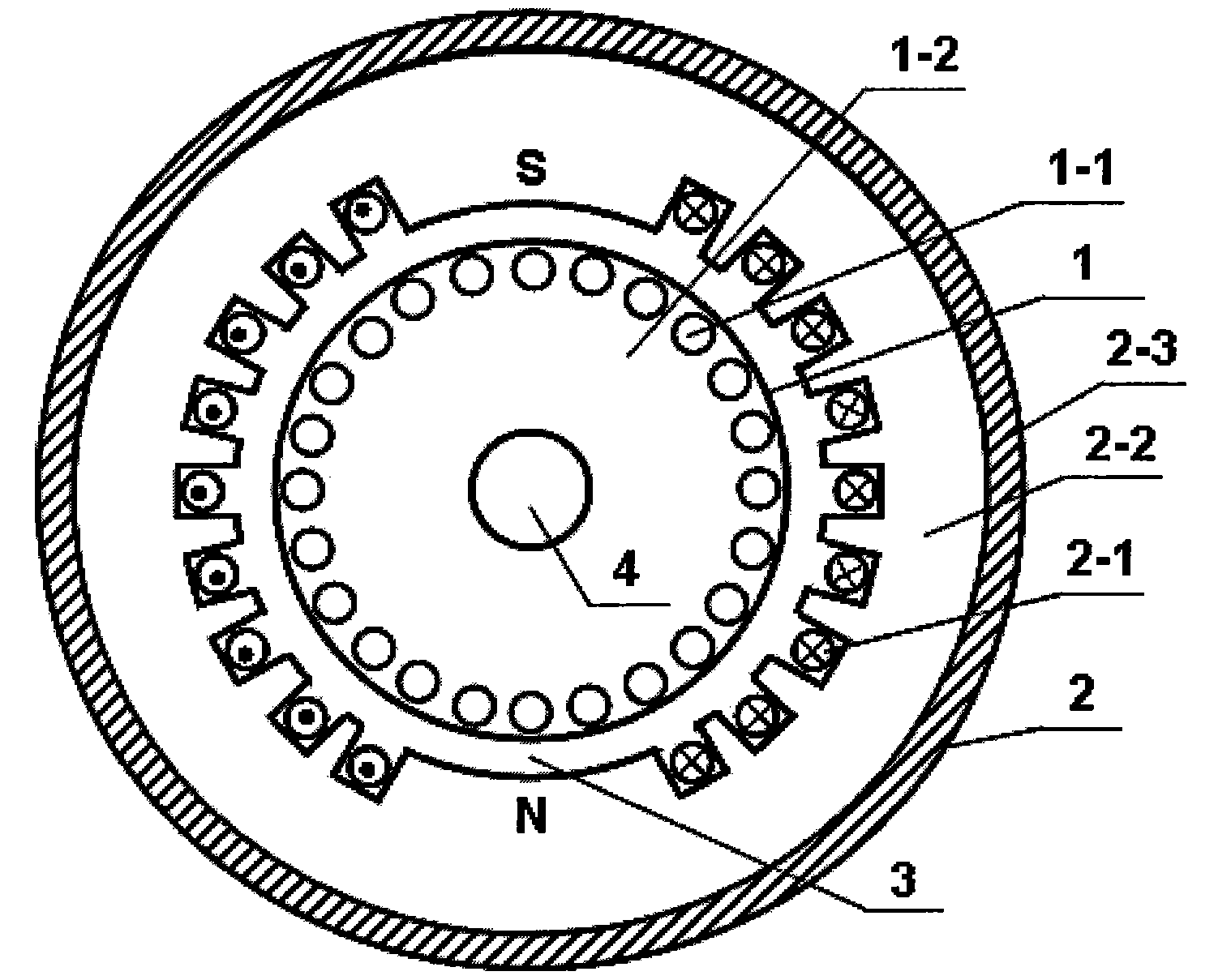
[0023] Refer to attached figure 1 , a hidden pole type electromagnetic speed regulator, characterized in that it includes an inner rotor 1, a hidden pole type outer rotor 2 and an inner rotor shaft 4, and a uniform gas with a fixed size is formed between the inner rotor and the hidden pole type outer rotor. Gap 3.

[0024] The inner rotor 1 includes an inner rotor winding 1-1 and an inner rotor core 1-2, which is the same as the rotor of a traditional AC asynchronous motor, and can be a squirrel-cage type, a wound type or a solid rotor; the inner rotor 1 is set on 4 on the inner rotor shaft, and make a whole with the inner rotor shaft 4.

[0025] The hidden pole type outer rotor 2 includes a distributed outer rotor excitation winding 2-1, a hidden pole type outer rotor core 2-2 and an outer rotor shell 2-3. The distributed outer rotor excitation winding 2-1 adopts copper or aluminum wires, and the hidden pole outer rotor iron core 2-2 adopts silicon steel sheet or alloy stee...

Embodiment 2

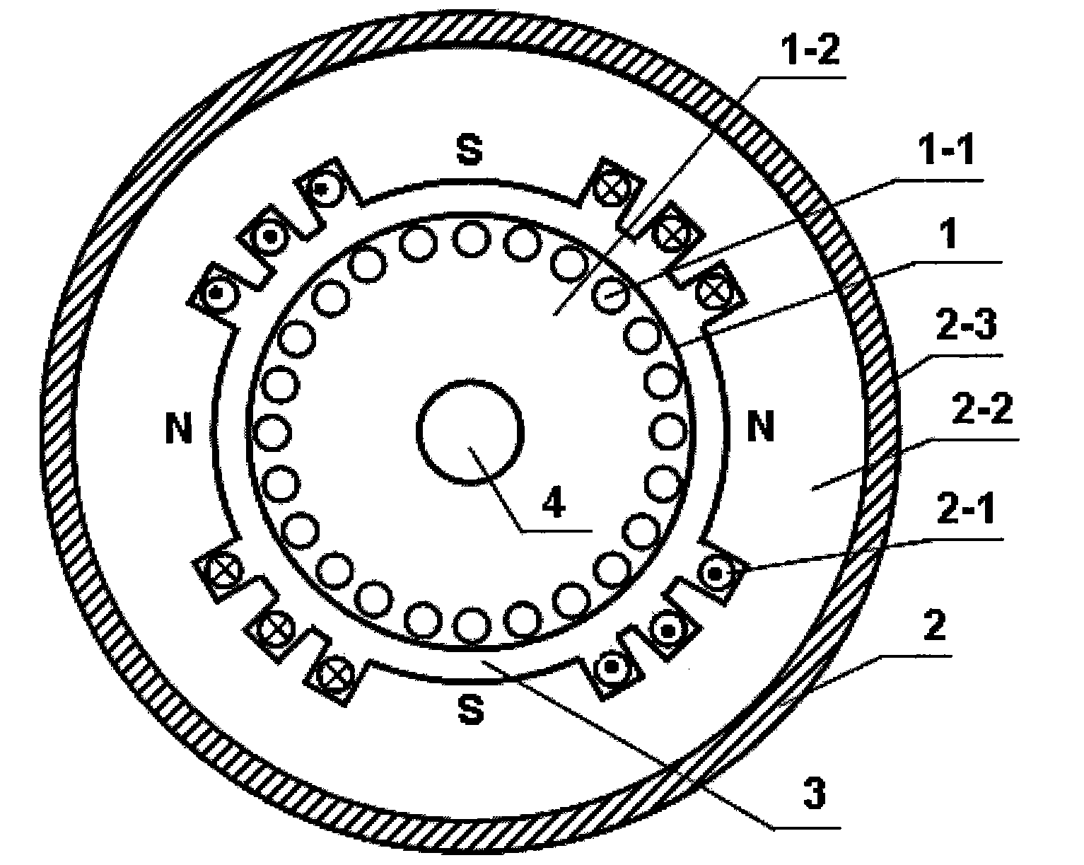
[0027] Refer to attached figure 2 , another embodiment of a hidden pole electromagnetic speed regulator. The two invisible iron core magnetic poles (one pair of poles) of the hidden pole type outer rotor 2 in the first embodiment are increased to four (two pairs of poles), by making the field winding 2-1 at both ends of each invisible iron core magnetic pole The direction of the current is opposite, so that the polarities of the two adjacent invisible iron core poles are opposite, forming a NSNS structure. By analogy, the number of invisible iron core poles can be increased to six (three pairs of poles), eight (four pairs of poles), ten (five pairs of poles), and so on.

Embodiment 3

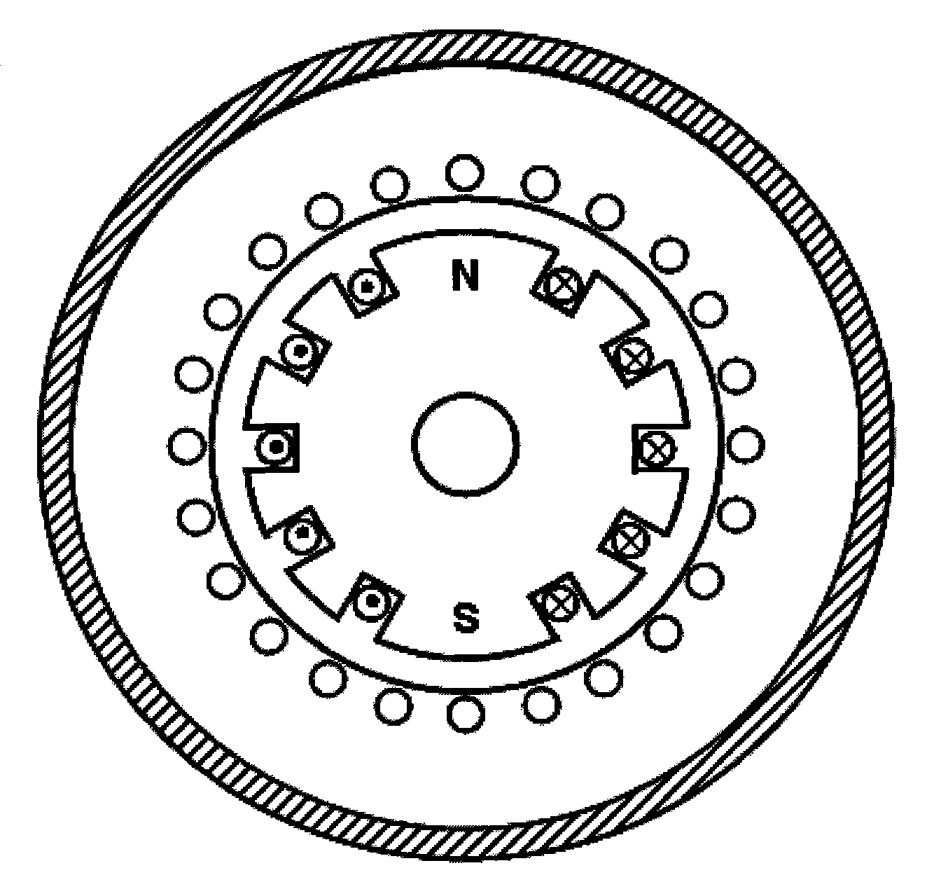
[0029] Refer to attached image 3 , another embodiment of a hidden pole electromagnetic speed regulator. The structures of the inner and outer rotors in Embodiment 1 are interchanged, that is, the outer rotor adopts the rotor structure of a traditional AC asynchronous motor, the inner rotor adopts a hidden-pole structure, and a DC excitation current is passed into the excitation winding of the hidden-pole inner rotor.


PUM


Abstract

A non-salient pole electromagnetic speed regulator is composed of an inner rotor, a non-salient pole outer rotor and an inner rotor shaft. Air gaps are evenly formed between the inner rotor and the outer rotor. The inner rotor comprises an inner rotor winding and an inner rotor iron core, and is the same as a rotor of a traditional alternating current asynchronous motor. The non-salient pole outer rotor comprises a distributed type outer rotor exciting winding, a non-salient pole outer rotor iron core and an outer rotor shell. An iron core slot is formed along the inner circle of the non-salient pole outer rotor iron core. The distributed type outer rotor exciting winding is embedded inside the iron core slot. The distributed type outer rotor exciting winding and an external direct current power source form a loop through a collecting ring and an electric brush which are installed on the outer rotor shell, and the distributed type outer rotor exciting winding can be supplied with direct current exciting current. The N pole and the S pole of a non-salient pole are formed at the unslotted part of the inner circle of the non-salient pole outer rotor iron core. The non-salient pole electromagnetic speed regulator has the advantages of replacing a frequency converter. A motor speed adjusting method is provided and is efficient, saving in energy, firm, reliable, low in cost, capable of achieving starting under no-load and free of electromagnetic interference.

Description

technical field [0001] The invention relates to an electromagnetic speed regulating machine, in particular to a hidden pole electromagnetic speed regulating machine, which can be widely used in various fields requiring speed regulating drives. Background technique [0002] According to statistics, my country's per unit energy consumption is five times that of developed countries, and it has remained high for a long time, and the serious waste of electric energy is one of the main reasons. Taking large-scale fans and water pumps as an example, the driving motor voltage is 3-10kV AC, and the power reaches more than 3000kW. In the past, a lot of electric energy was wasted due to the long-term use of constant-speed drive. When the fan and water pump output low flow, the motor runs at low speed, so that the power supply can achieve low power output, thereby saving electric energy. However, there are many restrictions on the use of variable frequency speed control power supply: F...

Claims


Application Information

Patent Timeline
Patent Type & Authority Applications(China)
IPC IPC(8): H02K16/02H02K1/26
Inventor 杨玉岗
Owner 杨玉岗
Learn More