
TM mode dielectric filter

A technology of dielectric filter and resonator, applied in the field of filter, can solve the problems of increasing production difficulty, difficult to reduce the volume, reducing reliability, etc., and achieve the effect of improving Q value, reducing loss and simple structure

Inactive Publication Date: 2014-06-11
WUHAN FINGU ELECTRONICS TECH
View PDF0 Cites 24 Cited by
  • Summary
  • Abstract
  • Description
  • Claims
  • Application Information

AI Technical Summary

Problems solved by technology

[0002] At present, the miniaturization of the filter volume has become a trend. The existing TM mode dielectric filter needs to introduce elastic conductors when using it, which increases the volume of the filter and makes the structure complex. The introduction of elastic conductors makes it difficult to reduce the volume. If it is forcibly reduced It will lead to reduced reliability and increased production difficulty

Method used


Image

  • TM mode dielectric filter
  • TM mode dielectric filter
  • TM mode dielectric filter

Examples


Embodiment

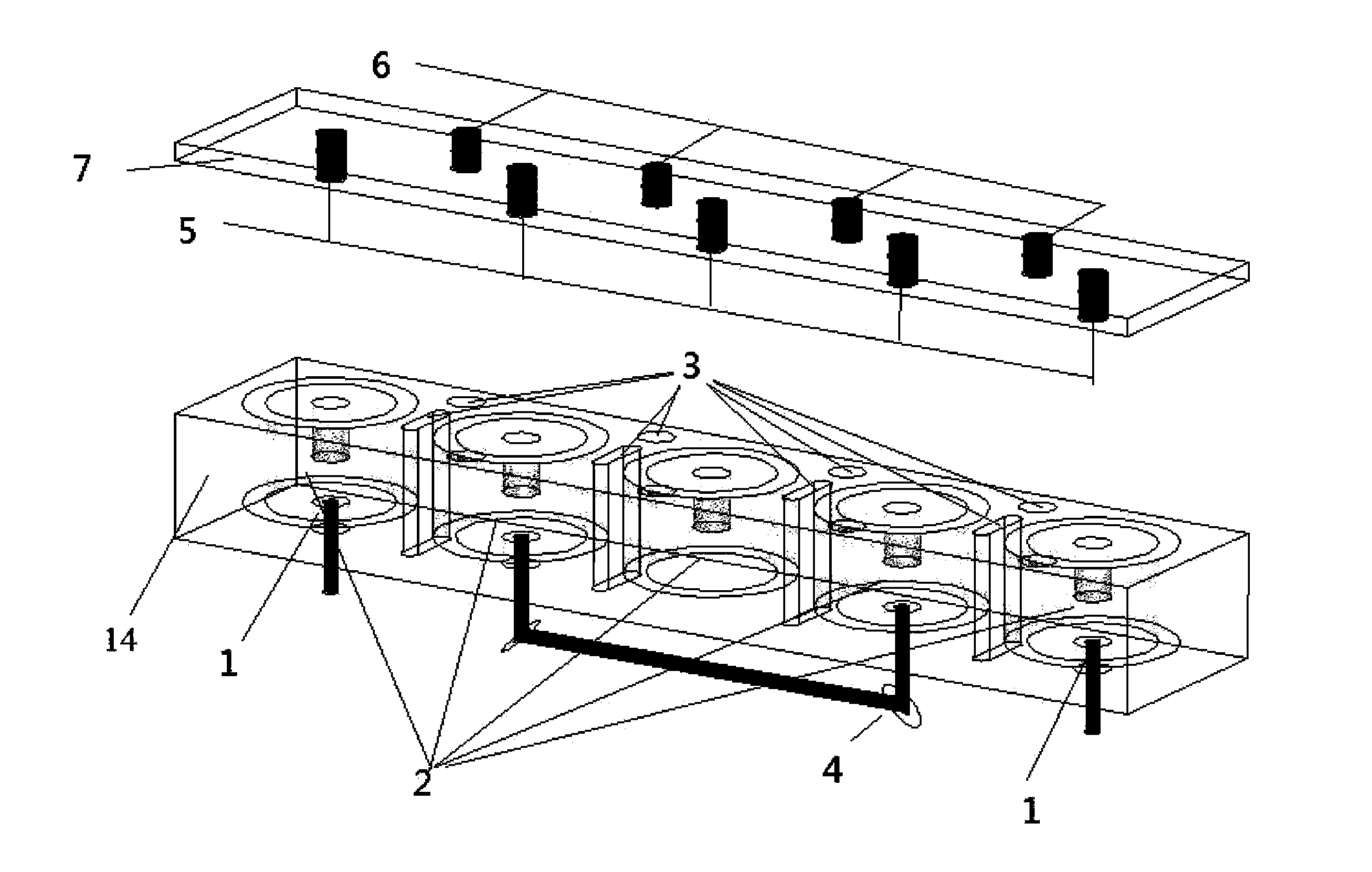
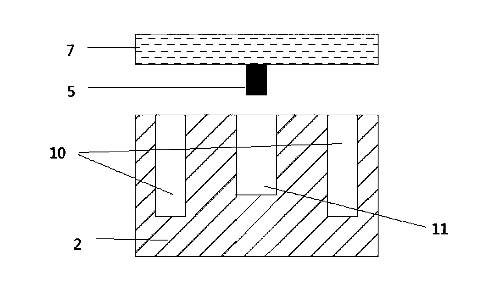
[0019] Example: such as figure 1 As shown, a TM-mode dielectric filter designed in the present invention includes a base 14 , at least three cylindrical resonators 2 arranged axially inside the base 14 and a cover plate 7 arranged on the top of the base 14 . The resonator 2 and the base 14 are integrally formed by TM mode dielectric material; the base 14 is provided with an annular air groove 10 with an open upper end around the cylindrical surface of the resonator 2 .

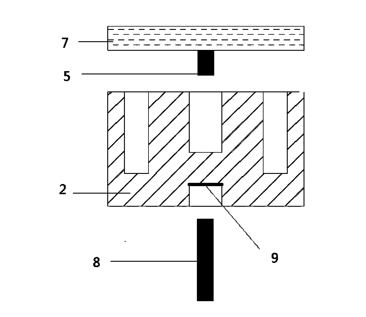
[0020] There is a frequency adjustment hole 11 on the resonator 2, and an inter-resonator coupling device 3 is provided between two adjacent resonators 2; a cross-coupling device 4 is provided between non-adjacent resonators 2, and the cross-coupling device 4 is Used to connect the transmission line at the bottom of the non-adjacent resonator 2, the transmission line can be a coaxial line, a microstrip line or a strip line, the contact surface between the transmission line and the bottom 2 of the resonator is ...


PUM


Abstract

The invention discloses a TM mode dielectric filter. The TM mode dielectric filter comprises a base and a covering plate, wherein at least two resonators are arranged in the base; frequency adjustment holes are formed in the resonators, and a resonator coupling device is arranged between every two adjacent resonators; the covering plate is provided with frequency adjustment screw rods corresponding to the frequency adjustment holes; the two resonators at the two ends in the base are respectively provided with an input and output coupling device. The TM mode dielectric filter is characterized in that resonators are cylindrical, and the resonators and the base are made of the same material and formed integrally; annular air grooves with upper ends open are formed circumferentially in the cylindrical surface of each resonator in the base; the base and the covering plate are made of TM mode dielectric material. The TM mode dielectric filter has the advantages of being simple in structure, free of introduction of elastic conductors, small in size, and better in filtering performance.

Description

technical field [0001] The invention relates to the field of filters, in particular to a TM mode dielectric filter. Background technique [0002] At present, the miniaturization of the filter volume has become a trend. The existing TM mode dielectric filter needs to introduce elastic conductors when using it, which increases the volume of the filter and makes the structure complex. The introduction of elastic conductors makes it difficult to reduce the volume. If it is forcibly reduced It will lead to reduced reliability and increased production difficulty. How to avoid the introduction of elastic conductors, miniaturize the size of the filter and improve the filtering effect is a long-term problem faced by those skilled in the art. Contents of the invention [0003] The object of the present invention is to solve the shortcomings of the above-mentioned background technology, and propose a TM mode dielectric filter with simple structure, no need to introduce elastic condu...

Claims


Application Information

Patent Timeline
IPC IPC(8): H01P1/201H01P1/208
Inventor 王一凡钟伟刚
Owner WUHAN FINGU ELECTRONICS TECH
Learn More