
Flow measuring pipe segment for small-caliber ultrasonic heat meter

A flow measurement and ultrasonic technology, applied in the field of sensing technology and flow measurement devices, can solve the problems of sealing, pressure resistance, pressure loss, anti-blocking, anti-corrosion and scaling cleaning, the relative size of components is difficult to meet the position accuracy requirements, and the reflection inside the pipe It can reduce the processing cost, improve the flow performance, and reduce the operating cost.

Inactive Publication Date: 2014-06-11
INNER MONGOLIA UNIV OF SCI & TECH
View PDF5 Cites 5 Cited by
  • Summary
  • Abstract
  • Description
  • Claims
  • Application Information

AI Technical Summary

Problems solved by technology

The composite pipe section is welded by straight pipe sections, transducer mounting holes, and converter mounting seats. The narrow space makes welding difficult, and the geometric deformation during welding will make it difficult for the relative dimensions of each component to meet the positional accuracy requirements. In addition, There are also problems in sealing, pressure resistance, pressure loss, anti-blocking, anti-corrosion and scaling cleaning.
The integrated casting pipe section has simple structure, high pressure bearing capacity, good sealing performance, no welding deformation, and can well ensure the consistency requirements of the measuring pipe section. It is not easy to clean after fouling, which will seriously affect the measurement accuracy, thereby reducing the accuracy of measurement

Method used


Image

  • Flow measuring pipe segment for small-caliber ultrasonic heat meter
  • Flow measuring pipe segment for small-caliber ultrasonic heat meter
  • Flow measuring pipe segment for small-caliber ultrasonic heat meter

Examples


Embodiment Construction

[0016] specific implementation plan

[0017] Below in conjunction with accompanying drawing, the present invention will be further described through embodiment.

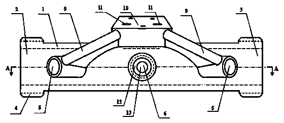
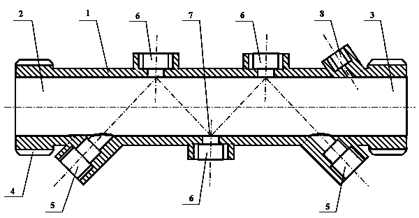
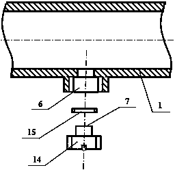
[0018] Such as Figure 1-3 As shown, the straight pipe section 1 for flow measurement is integrally cast from copper alloy. The straight pipe section 1 is cylindrical as a whole and adopts a straight-through structure with the same diameter. The straight pipe section 1 is provided with two transducer mounting holes 5, Three reflective plug installation holes 6, one temperature sensor installation hole 8, two wire threading pipes 9 and one converter installation seat 10, and the inner surface of the straight pipe section 1 is polished.

[0019] The straight pipe section 1 is provided with two transducer installation holes 5 and three reflection plug installation holes 6, and the included angle between the centerline of the transducer installation holes 5 and the centerline of the straight pipe section 1 is 45° o , t...


PUM


Abstract

The invention relates to a flow measuring pipe segment for a small-caliber ultrasonic heat meter, and belongs to the field of sensing technology and flow metering devices. A straight pipe segment is cast by using a copper alloy, and is provided with two energy transducer mounting holes, three reflecting pipe plug mounting holes, a temperature sensor mounting hole, two conduits and a converter mounting base; energy transducers and reflecting pipe plugs are arranged horizontally, and are centered one above another. Ultrasonic waves are reflected for three times by three reflecting pipe plugs from transmission to receiving, so that the flow measuring accuracy of a small-caliber pipeline is increased. The reflecting pipe plugs and energy transducers are sealed by annealed red copper gaskets of specific sizes, so that the sealing performance and the mounting accuracy are ensured. The reflecting pipe plugs and the straight pipe segment are the same in material, and the reflecting pipe plugs can be detached, so that water scales on the surfaces can be cleaned conveniently. The reflecting surface is extremely high in smoothness, so that the reflecting effect is ensured. Protrusion does not exist in a pipe, so that the pressure loss is extremely low. The converter mounting base is positioned above the straight pipe segment, and inclines forwards by 45 degrees, so that convenience is brought to installation, reading, maintenance and management of a converter.

Description

technical field [0001] The invention belongs to the field of sensing technology and flow metering devices, and in particular relates to a small-diameter ultrasonic heat meter flow measuring pipe section. Background technique [0002] The existing ultrasonic heat meter flow sensor is usually composed of a flow measuring pipe section, an ultrasonic transducer and a reflector. According to the arrangement of ultrasonic channels, it can be divided into three types: parallel method, direct transmission method and reflection method. The ultrasonic propagation direction of the parallel method is parallel to the axis of the pipe section (that is, the direction of water flow), and the detected flow velocity is the flow velocity at the position coincident with the sound channel in the water flow section, and does not represent the average velocity in the pipeline. The propagation direction intersects the axis of the pipe section (that is, the direction of water flow) (for example, th...

Claims


Application Information

Patent Timeline
Patent Type & Authority Applications(China)
IPC IPC(8): G01F1/66G01F15/00G01K17/06
Inventor 李忠虎
Owner INNER MONGOLIA UNIV OF SCI & TECH
Learn More