
Electronic controller and fadec system based on time trigger protocol ttp/c bus

A technology of time-triggered protocol and electronic controller, applied in machine/engine, jet propulsion, gas turbine, etc., can solve problems such as difficulty in fault detection, increase in development cost, complex configuration, etc., to reduce processing burden, The effect of improving reliability and simple wiring

Active Publication Date: 2016-04-20
AECC COMML AIRCRAFT ENGINE CO LTD
View PDF6 Cites 1 Cited by
  • Summary
  • Abstract
  • Description
  • Claims
  • Application Information

AI Technical Summary

Problems solved by technology

[0003] (1) Due to the need for various buses to participate in the data exchange between the board levels, the wiring becomes complicated and the anti-interference performance is poor;
[0004] (2) Since the calculation and control module has a large number of trigger events to be processed, low-priority events are not easy to be processed, and it is very difficult to develop, test, and verify real-time tasks such as data acquisition preprocessing, control, and diagnosis;
[0005] (3) Data exchange between boards through parallel bus increases the difficulty of fault detection and brings great challenges to the design of fault isolation and reconstruction;
[0006] (4) Module reusability is poor, and most modules must be redesigned and verified when designing a new FADEC system, which reduces development efficiency and increases development costs
[0012] c) The ARINC664 bus requires a switch to realize multi-node interconnection, the configuration is complex, and it is not suitable for the distributed architecture in the machine
[0013] d) The EtherCAT bus has a master-slave architecture. Once the bus master control unit fails, the entire network will not work normally and does not support redundant management
[0014] e) The ARINC659 bus supports time triggering and has high reliability, but the implementation of the protocol depends on the physical layer and does not support CRC check
[0015] In order to solve the problems of poor reusability, high complexity, and unfavorable maintenance of centralized electronic controllers, it is necessary to design a new type of distributed electronic controller architecture in the machine

Method used


Image

  • Electronic controller and fadec system based on time trigger protocol ttp/c bus
  • Electronic controller and fadec system based on time trigger protocol ttp/c bus
  • Electronic controller and fadec system based on time trigger protocol ttp/c bus

Examples


Embodiment Construction

[0036] The present invention will be described more fully hereinafter with reference to the accompanying drawings, in which exemplary embodiments of the invention are illustrated. The following will clearly and completely describe the technical solutions in the embodiments of the present invention with reference to the accompanying drawings in the embodiments of the present invention. Obviously, the described embodiments are only some of the embodiments of the present invention, not all of them. Based on the embodiments of the present invention, all other embodiments obtained by persons of ordinary skill in the art without making creative efforts belong to the protection scope of the present invention.

[0037] Time-triggered protocol TTP / C is a physical implementation mechanism based on time-triggered and highly reliable systems. The research group of Professor H. Kopetz of the Vienna University of Technology developed the TTP / C protocol, which stands for Time-Triggered Proto...


PUM


Abstract

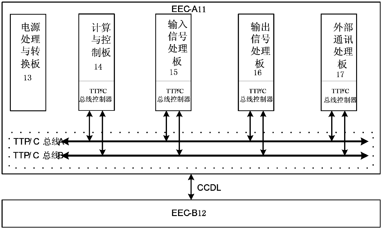
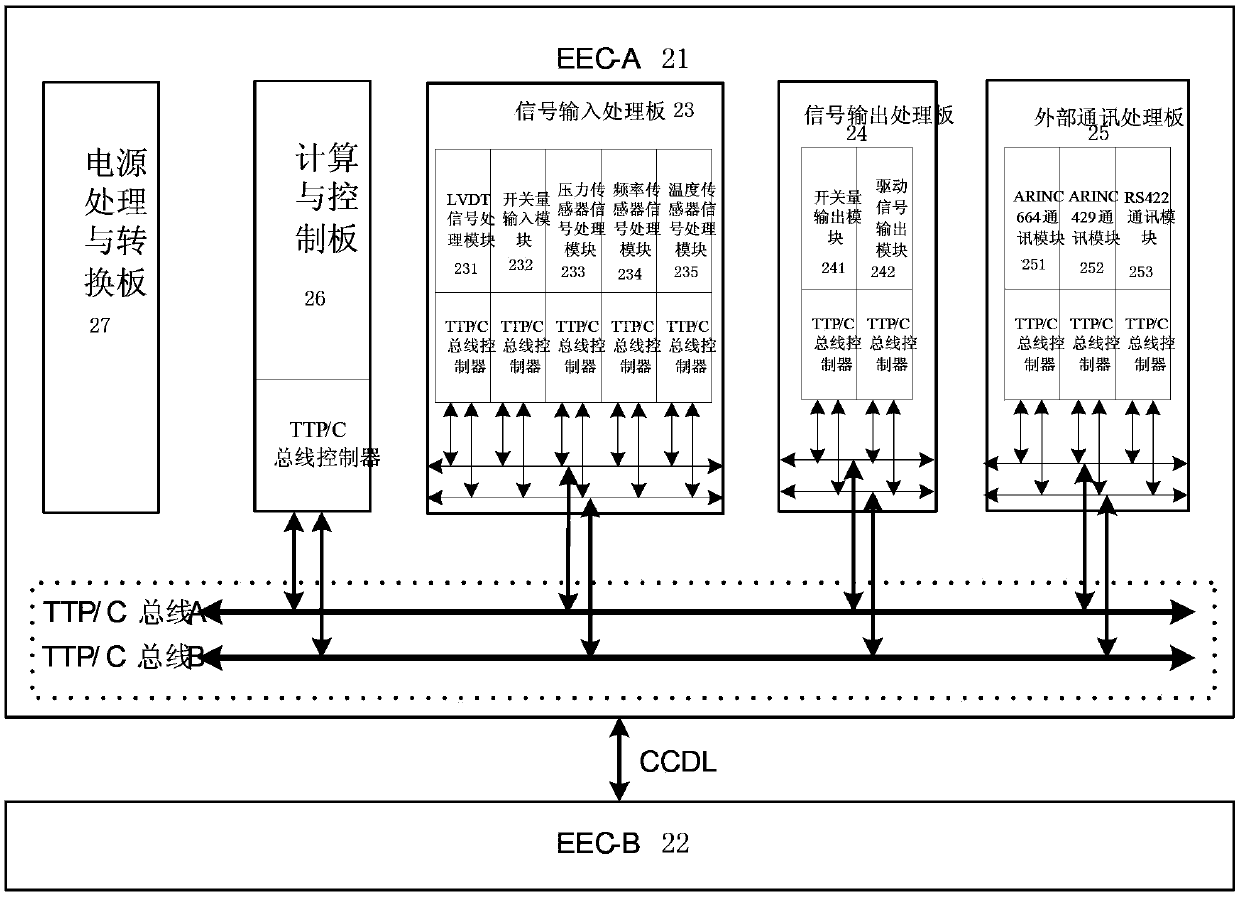
The invention discloses a TTP / C bus-based electronic controller and an FADEC system. Each of the two groups of functional units which are redundant to each other comprises multiple functional daughter boards and inter-board TTP / C buses, each functional daughterboard is integrated with a TTP / C bus controller and the TTP / C bus controllers are connected with the inter-board TTP / C buses, thus the data interaction among functional daughter boards is realized. According to the TTP / C bus-based electronic controller and the FADEC system, buses are adopted for data exchange among the boards, the wiring becomes easy, the interference among the boards is small and the processing burdens of computing and a control board are reduced; by adopting time-triggered protocol, broadband for various tasks can be assigned in real time, the reliability of the whole machine is increased and the design can be more flexible.

Description

technical field [0001] The invention relates to the technical fields of engine control and computer bus, in particular to an electronic controller and FADEC system based on the time trigger protocol TTP / C bus. Background technique [0002] The electronic controllers in the current mainstream aero-engine FADEC (FullAuthorityDigitalEngineControl: Full Authority Digital Electronic Control) systems generally adopt a centralized dual-channel redundant architecture, and the board-level directly participates in board-level information exchange through the control bus, address bus, and data bus. The computing resources of this architecture are highly concentrated on the computing and control modules inside the chassis, which will bring the following problems: [0003] (1) Due to the need for various buses to participate in the data exchange between the board levels, the wiring becomes complicated and the anti-interference performance is poor; [0004] (2) Since the calculation and ...

Claims


Application Information

Patent Timeline
Patent Type & Authority Patents(China)
IPC IPC(8): F02C9/00
Inventor 张树彦吕晓武张哲殷锴李运华
Owner AECC COMML AIRCRAFT ENGINE CO LTD
Learn More