
Simple precision die

A fine punching die, a simple technology, applied in the field of stamping dies, can solve problems affecting stability, strip shearing and tearing, affecting stamping accuracy, etc., to achieve the effect of enhancing compression resistance, increasing compression resistance, and ensuring stamping accuracy

Inactive Publication Date: 2014-06-11
KUNSHAN PANTRATEQ
View PDF6 Cites 3 Cited by
  • Summary
  • Abstract
  • Description
  • Claims
  • Application Information

AI Technical Summary

Problems solved by technology

[0002] Stamping die is a kind of equipment commonly used in industrial production. It can perform forming processes such as punching and blanking. When the existing stamping die punches thin materials, the material belt is in a free state. When punching or blanking, the material belt is very fast. It is easy to wrinkle, which affects the accuracy of the product and increases the reject rate of the product. Even if the unloading plate is used to press the unloading and pushing parts, the pressure on the material belt is not enough to prevent the material belt from bending
In addition, when the existing stamping die is used for stamping, the material strip is only subjected to the pressure of the punch, and the material strip at the edge will be sheared and torn. The product section is only about 1 / 3 of the bright band, and the rest is rough fracture. Belt, poor section quality
[0003] Patent No. 201120025855.1 discloses a simple fine punching die, which can increase the pressure on the material strip during stamping, make the material strip in a state of three-dimensional compressive stress, prevent the material strip from bending, and improve the precision and section quality of the product, but The lower end of the top plate set in the die is only provided with two ejector pins, the bearing pressure is not enough, it can only withstand the pressure on thin materials, and it is easy to cause the ejector pins to break for thick materials; in addition, the punch and the upper die, There is only one screw at the connection between the die and the bottom die, which affects its stability. The die is prone to deviation during the stamping process, which affects its stamping accuracy

Method used


Image

  • Simple precision die

Examples


Embodiment Construction

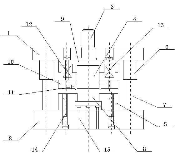
[0010] see figure 1 , the specific embodiment adopts the following technical solutions: it includes an upper die base 1, a lower die base 2, a handle 3, a punch 4, a die 5, a guide sleeve 6, a guide post 7, a top plate 8, a backing plate 9, an unloading Material plate 10, ring gear platen 11, upper mold base 1 is provided with mold handle 3, between upper mold base 1 and lower mold base 2 is provided with guide sleeve 6 and guide post 7, guide post 7 and guide sleeve 6 are flexibly connected , the lower end of the upper die base 1 is provided with a punch 4, a backing plate 9 is arranged between the punch 4 and the upper die base 1, a discharge plate 10 is arranged on the lower side of the punch 4, and the lower end of the discharge plate 10 is provided with Annular opening, ring gear pressing plate 11 is arranged in the annular opening, die 5 is provided with top plate 8 in the middle, and the lower end of top plate 8 is provided with three ejector pins 15, and die 5 is fixed...


PUM


Abstract

A simple precision die relates to the field of punching equipment. A die handle is arranged on an upper die holder, guide sleeves and guide posts are arranged between the upper die holder and a lower die holder, the guide posts are movably connected with the guide sleeves, a male die is arranged on the bottom of the lower die holder, a bolster is arranged between the male die and the upper die holder, a stripper plate is arranged on the lower part of the male die, the bottom of the stripper plate is provided with an annular opening, a toothed ring pressing plate is arranged in the annular opening, an ejector plate is arranged at the middle of a female die, three ejector rods are arranged on the bottom of the ejector plate, and the female die is fixed on the top of a lower die holder by a left screw and a right screw. Two stripper screws are arranged between the upper die holder, the bolster and the stripper plate, and disc springs are arranged on the stripper screws. The simple precision die can overcome the defects of the prior art, the pressure resistance of the simple precision die is enhanced, the deviation of the die is prevented, and thereby the punching precision of the die is ensured.

Description

Technical field: [0001] The invention relates to a stamping die, in particular to a simple fine punching die. Background technique: [0002] Stamping die is a kind of equipment commonly used in industrial production. It can perform forming processes such as punching and blanking. When the existing stamping die punches thin materials, the material belt is in a free state. When punching or blanking, the material belt is very fast. It is easy to wrinkle, which affects the accuracy of the product and increases the reject rate of the product. Even if the unloading plate is used to press the unloading and pushing parts, it cannot prevent the material belt from bending because of insufficient pressure on the material belt. In addition, when the existing stamping die is used for stamping, the material strip is only subjected to the pressure of the punch, and the material strip at the cutting edge will be sheared and torn. The product section has only about 1 / 3 of the bright band, an...

Claims


Application Information

Patent Timeline
Patent Type & Authority Applications(China)
IPC IPC(8): B21D37/10
Inventor 杨东明
Owner KUNSHAN PANTRATEQ
Learn More