
System and method for calculating time lag stability upper limit based on generalized eigenvalue

A generalized eigenvalue and time-delay system technology, applied in the field based on generalized eigenvalues, can solve high conservatism problems

Active Publication Date: 2014-06-04
NORTH CHINA ELECTRIC POWER UNIV (BAODING)
View PDF4 Cites 11 Cited by
  • Summary
  • Abstract
  • Description
  • Claims
  • Application Information

AI Technical Summary

Problems solved by technology

[0006] The object of the present invention is to provide a time-delay stability upper limit calculation system and calculation method based on generalized eigenvalues, which are used to solve the problem of high conservatism in the process of solving the time-delay upper limit by the direct method

Method used


Image

  • System and method for calculating time lag stability upper limit based on generalized eigenvalue
  • System and method for calculating time lag stability upper limit based on generalized eigenvalue
  • System and method for calculating time lag stability upper limit based on generalized eigenvalue

Examples


Embodiment 1

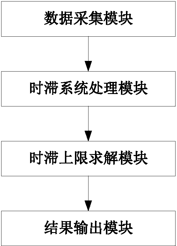
[0060] figure 1 It is a structural diagram of the calculation system of the time-delay stability upper limit based on the generalized eigenvalue provided by the present invention. Such as figure 1 As shown, the structure diagram of the time-delay stability upper limit calculation system based on generalized eigenvalues ​​provided by the present invention includes sequentially connected data acquisition modules, time-delay system processing modules, time-delay upper limit solution modules and result output modules.

[0061] The data collection module is used to collect network structure parameters, generator frequency and generator power angle, and send the collected data to the time-delay system processing module. Among them, the network structure parameters are the parameters needed to establish the state equation of the time-delay system, and the generator frequency and generator power angle are the state vectors in the state equation of the time-delay system.

[0062] The...

Embodiment 2

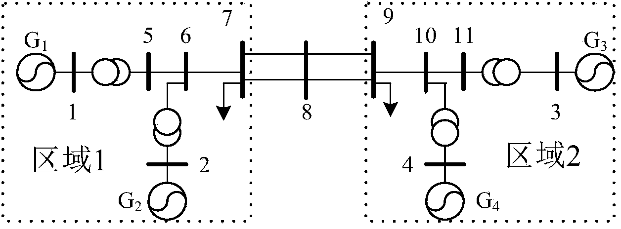
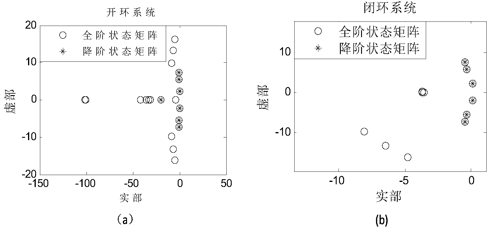
[0145] Built based on MATLAB simulation software figure 2 In the IEEE4-machine 11-node system shown, the generator adopts a 6-order detailed model, the excitation system adopts fast excitation, and the load under the benchmark model adopts a 50% constant impedance and 50% constant current model. First, the state matrix of the four-machine system is obtained by the modal analysis method, and the SMA method is used to reduce the order of the open-loop and closed-loop state matrices, as shown in image 3 shown.

[0146] image 3 (a) is a comparison diagram of the characteristic roots of the full-order open-loop state matrix and the reduced-order open-loop state matrix, and (b) is a comparison diagram of the characteristic roots of the full-order closed-loop state matrix and the reduced-order closed-loop state matrix. Depend on image 3 It can be seen that the low-frequency oscillation components in the system are retained after the order reduction of the open-loop and closed-...

Embodiment 3

[0154] Built based on MATLAB simulation software Figure 8 The shown IEEE16-machine 68-node system further examines the validity and versatility of the maximum time-delay solution method based on the generalized eigenvalue method. The important connection lines of this system are the connection lines 1-2, 1-27 and 8-9 of Area 4 and Area 5. The generator adopts a 6-order detailed model, the excitation adopts IEEE-DC1 type excitation, the load model is 15% constant active power, 25% constant active current and 15% constant reactive power, 25% constant reactive power and 60% constant impedance. First, the Schur balance reduction method is used to reduce the order of the system under the premise that the input and output characteristics of the frequency band of interest remain unchanged, such as Figure 9 shown.

[0155] Figure 9 (a) The solid line is the frequency response of the open-loop full-order system, and the dashed line is the frequency response of the open-loop redu...


PUM


Abstract

The invention discloses a system and method for calculating the time lag stability upper limit based on the generalized eigenvalue and belongs to the technical field of analysis of the stability of an electric power system. The system for calculating the time lag stability upper limit based on the generalized eigenvalue comprises a data acquisition module, a time lag system processing module, a time lag upper limit solving module and a result output module, wherein the data acquisition module, the time lag system processing module, the time lag upper limit solving module and the result output module are connected in sequence. The method for calculating the time lag stability upper limit based on the generalized eigenvalue comprises the steps that network structural parameters, the frequency of an electric generator and the power angle of the electric generator are collected, wherein the network structural parameters, the frequency of the electric generator and the power angle of the electric generator are needed for establishing a time lag system state equation; the time lag system state equation is established, order reduction is conducted on a parameter matrix in the time lag system state equation, and a time lag system state equation with the order reduced is obtained; a time lag stability criterion based on an improved free weight matrix is generated; the time lag stability upper limit is solved according to the time lag stability criterion. According to the system and method for calculating the time lag stability upper limit based on the generalized eigenvalue, the conservation of time lag stability upper limit calculation can be effectively reduced, and the correctness and effectiveness are high.

Description

technical field [0001] The invention belongs to the technical field of power system stability analysis, in particular to a method based on generalized eigenvalues [0002] A time-delay stable upper limit calculation system and a calculation method thereof. Background technique [0003] The design of the feedback controller based on wide-area information has time-delay problems, which will inevitably lead to the decrease of the control effect of the controller, and even the occurrence of negative damping. Therefore, it is urgent to study the upper limit of the system's time-delay stability. [0004] At present, scholars at home and abroad have made a lot of beneficial results in the study of the upper limit of system time-delay stability, which can be mainly divided into three categories: time domain method, frequency domain method and direct method. The time-domain method can determine whether the system is stable in a specific scenario, but further research is needed on t...

Claims


Application Information

Patent Timeline
IPC IPC(8): G06F19/00
Inventor 马静李俊臣高翔丁秀香王增平
Owner NORTH CHINA ELECTRIC POWER UNIV (BAODING)
Learn More