
A miniature near-eye display optical system

A near-eye display and optical system technology, which is applied in optics, optical components, instruments, etc., can solve the problem that the compactness of the head-mounted display needs to be further improved, and achieve a compact and light structure that is conducive to market promotion and application. compact effect

Active Publication Date: 2017-01-18
HANGZHOU KOTI OPTICAL TECH
View PDF2 Cites 0 Cited by
  • Summary
  • Abstract
  • Description
  • Claims
  • Application Information

AI Technical Summary

Problems solved by technology

Although this technical solution simplifies the structure and effectively saves the cost, the compactness of the head-mounted display still needs to be further improved

Method used


Image

  • A miniature near-eye display optical system
  • A miniature near-eye display optical system
  • A miniature near-eye display optical system

Examples


Embodiment Construction

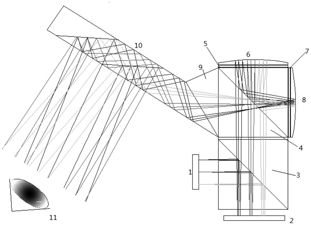
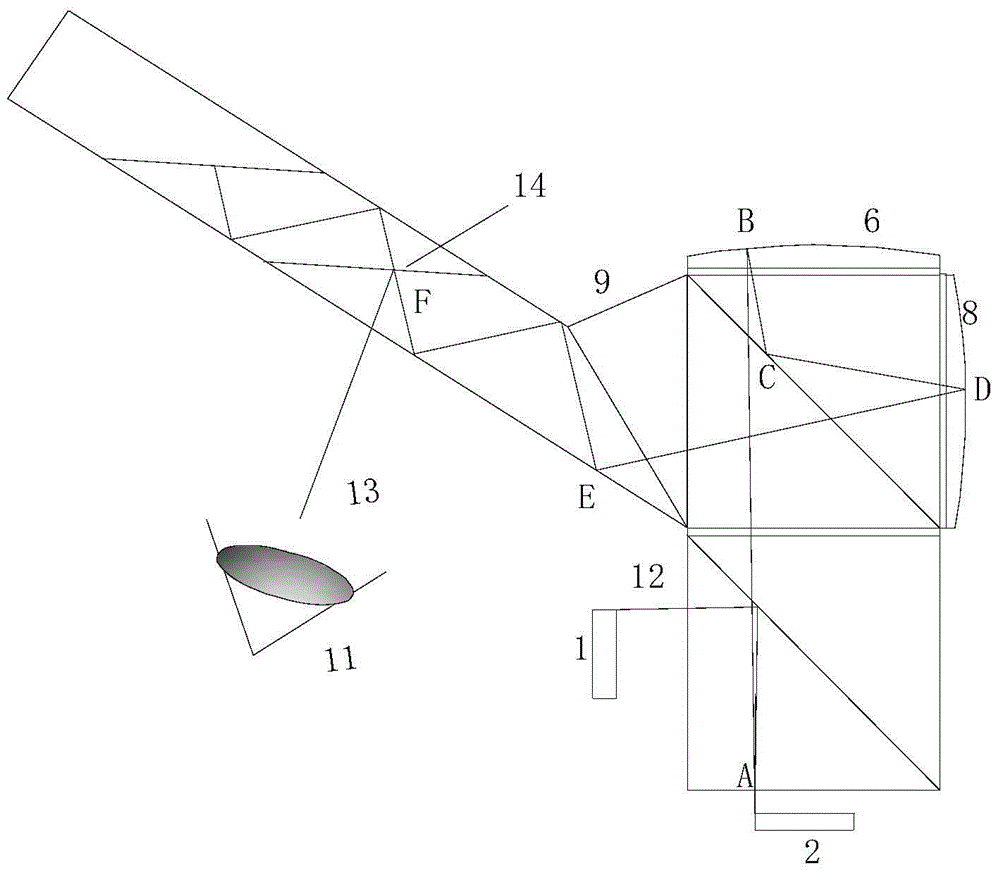
[0034] figure 1 It is a structural schematic diagram of a miniature near-eye display optical system of the present invention. Such as figure 1As shown, along the direction of light propagation, the miniature near-eye display optical system sequentially includes an LED light source 1, a first polarizing beam splitter 3, an LCOS image source 2, a second polarizing beam splitter 4, a first 1 / 4 wavelength plate 5, The first reflector 6, the second 1 / 4 wavelength plate 7, the second reflector 8, the coupling prism 9 and the waveguide device 10, finally, the human eye 11 is used to receive the image light signal of the miniature near-eye display optical system of the present invention. Specifically, the LCOS image source 2 is used to provide images, the LED light source 1 is used to provide a light source for the LCOS image source 2, and the first polarizing beam splitter 3 is used to reflect the S light of the LED light source 1 onto the LCOS image source 2 and allow The P light ...


PUM


Abstract

The invention discloses a minitype near-to-eye display optical system which comprises an LCOS image source for providing images, an LED light source, a first polarization beam splitter, a second polarization beam splitter, a first 1 / 4 wavelength plate, a first reflector, a second 1 / 4 wavelength plate, a second reflector, a coupling prism and a P light waveguide device. The first polarization beam splitter reflects S light of the LED light source to the LCOS image source, and P light emitted by the LCOS image source passes through the first polarization beam splitter. The second polarization beam splitter is used for reflecting the P light which passes through the first polarization beam splitter and the S light. The first 1 / 4 wavelength plate is used for receiving the P light which passes through the second polarization beam splitter. The first reflector is used for reflecting the P light, and the P light passes back through the first 1 / 4 wavelength plate. The second 1 / 4 wavelength plate is used for receiving the S light which passes back through the first 1 / 4 wavelength plate and is reflected by the second polarization beam splitter. The P light waveguide device is used for receiving P light output from the coupling prism. The minitype near-to-eye display optical system is compact in structure and light, a large visual field is achieved, and wide application prospect is achieved.

Description

technical field [0001] The invention relates to the field of optical equipment for display, in particular to a miniature near-eye display optical system. Background technique [0002] The near-eye display system, also known as the head-mounted display, is a visual display that is used for virtual reality and other displays on the user's head. It was originally used in military and scientific research fields. With the advancement of technology and social development, people There is more and more understanding and learning of near-eye display technology, and near-eye display technology has gradually entered people's lives. Combining virtual display technology and augmented reality technology, the application field of near-eye display technology has expanded to education, training, commercial exhibitions, medical treatment, entertainment, etc. [0003] Along with the development of display devices, the size and weight of imaging devices are also decreasing. The near-eye disp...

Claims


Application Information

Patent Timeline
Patent Type & Authority Patents(China)
IPC IPC(8): G02B27/01G02B27/28
Inventor 杨晓华郑臻荣艾曼灵金波陶占辉李小瑞
Owner HANGZHOU KOTI OPTICAL TECH
Learn More