Eureka AIR delivers breakthrough ideas for toughest innovation challenges, trusted by R&D personnel around the world.

Aircraft magnetic disturbance field model parameter calculating method

A technology of model parameters and magnetic interference, applied in the direction of the magnitude/direction of the magnetic field, can solve problems such as model solution errors, neglect of aircraft motion coupling phenomena, and small intensity changes

Inactive Publication Date: 2014-06-04
HARBIN ENG UNIV
View PDF7 Cites 30 Cited by
  • Summary
  • Abstract
  • Description
  • Claims
  • Application Information

AI Technical Summary

Problems solved by technology

[0004] In the aspect of eliminating the magnetic interference field of the aircraft, many scholars have carried out relevant research, among which the aeromagnetic compensation scheme proposed by Leliak is the most classic, and it is still used as a standard method to overcome this type of interference. The interference model established by Leliak rotates the attitude of the carrier It is divided into three types: standard pitch, roll, and yaw, and each type of movement is considered separately. Before the carrier performs normal magnetic field measurement flight, a standard calibration flight is first carried out in a specific area to use the carrier interference field model parameters. However, this method has two main problems. One is that it ignores the unavoidable motion coupling phenomenon during the actual flight of the aircraft, so that the solution of the model will bring a certain error; Small
This will face greater difficulties and limitations in practical applications

Method used


Image

  • Aircraft magnetic disturbance field model parameter calculating method
  • Aircraft magnetic disturbance field model parameter calculating method
  • Aircraft magnetic disturbance field model parameter calculating method

Examples


Embodiment

[0088]During the implementation of the experiment, there are two main sources of unpredictable magnetic field measurement error interference: one is the random magnetic field interference in the experimental environment; the other is the measurement error of the magnetic sensor. In the experiment, the following interference fields and error sources are fully considered:

[0089] (1) And set the random magnetic field interference of the experimental environment to be Gaussian noise with a mean value of 2nT and a variance of 1 on each axial component;

[0090] (2) Set the measurement error of the magnetic sensor in each axis to a random value within [-33]nT.

[0091] (3) Set the error of the magnetic field generator as Gaussian noise with a mean value of 0nT and a variance of 2.

[0092] At the same time, under the condition of no interference, the projected components of the experimental environment magnetic field on the x-axis (due east), y-axis (due north), and z-axis (verti...


PUM


Abstract

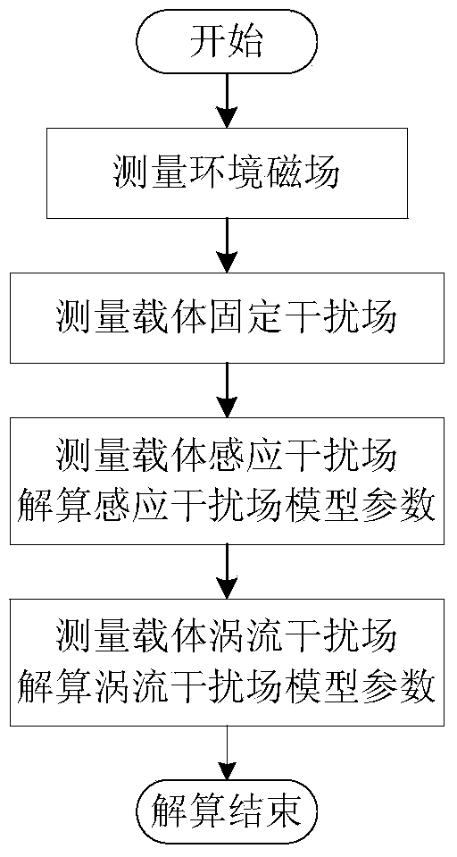
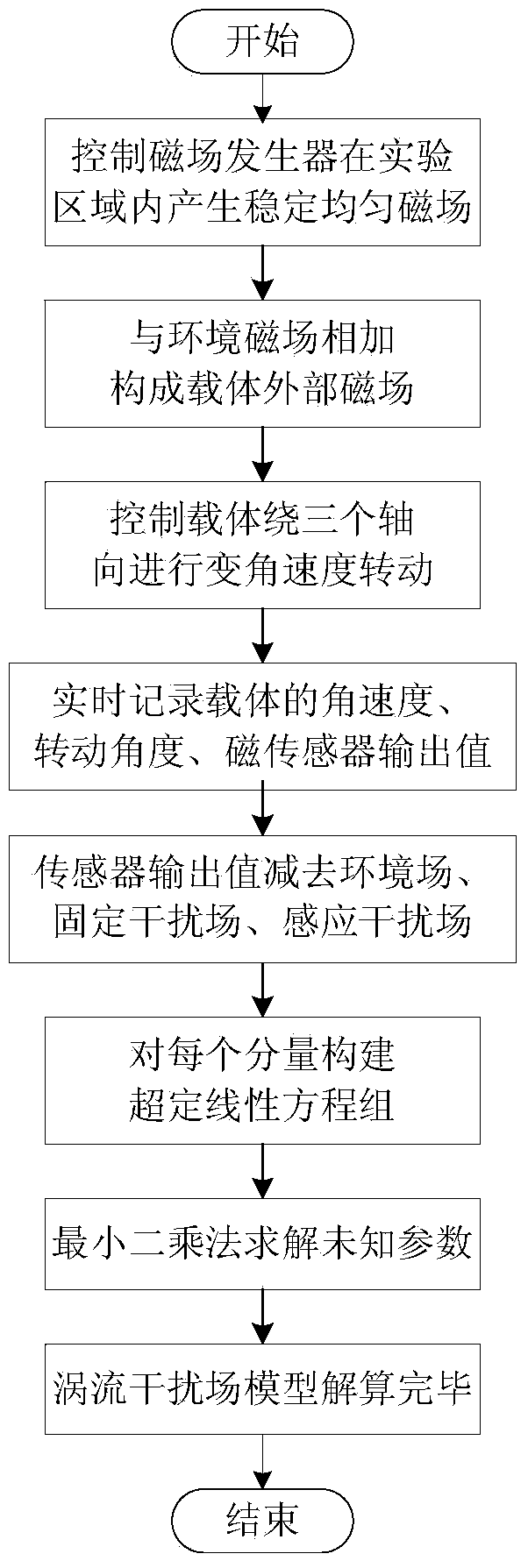
The invention belongs to the field of compensation for aircraft magnetic disturbance fields, and particularly relates to an aircraft magnetic disturbance field model parameter calculating method. The aircraft magnetic disturbance field model parameter calculating method comprises the steps of measuring an environment magnetic field of a tested area, measuring a fixed magnetic field and an inductive interference field of a carrier, calculating model parameters of the inductive interference field, measuring a vortex interference field of the carrier, and calculating model parameters of the vortex interference field. The three magnetic disturbance fields of the carrier are measured and calculated gradually in the testing process, and testing pertinence is enhanced; calculating errors caused by the carrier movement coupling according to a traditional method are avoided by effectively controlling the carrier to move; calibration flying necessary in the traditional method is avoided through off-line tests and calculation, and testing resources are saved; the magnetic field of the testing environment can be effectively controlled, and errors caused by the unstable magnetic field of the tested area according to the traditional method are avoided.

Description

technical field [0001] This research belongs to the field of aircraft magnetic interference field compensation, and specifically involves a parameter calculation method for aircraft magnetic interference field model. Background technique [0002] The geomagnetic field plays an increasingly important role in engineering and military applications. Whether it is the surveying and mapping of geomagnetic maps, mineral resource detection, carrier geomagnetic navigation, and anti-submarine detection, etc., they are all based on accurate geomagnetic field measurements. However, when an aircraft is equipped with a magnetometer for magnetic field measurement, it will inevitably be interfered by its own carrier. . This is because the carrier contains a large amount of ferromagnetic substances. Even if this interference can be effectively reduced by improving the carrier material and the configuration of the magnetic sensor on the carrier, it is still unacceptable for high-precision en...

Claims


Application Information

Patent Timeline
IPC IPC(8): G01R33/02
Inventor 赵玉新常帅张瑶贾韧锋杜雪李旺吴迪张靖靖
Owner HARBIN ENG UNIV
Why Eureka
Eureka Blog
Learn More