
Detection equipment

A technology for testing equipment and control boxes, which is applied in the direction of measuring devices, optical testing of defects/defects, and material analysis through optical means, and can solve problems such as the inability to obtain the specific conditions of the inner wall of the pipeline

Active Publication Date: 2014-06-04
CHENGDU ZHIRONG ZHICHUANG INTPROP MANAGEMENT CO LTD
View PDF7 Cites 4 Cited by
  • Summary
  • Abstract
  • Description
  • Claims
  • Application Information

AI Technical Summary

Problems solved by technology

[0003] The purpose of the present invention is to overcome the problem that the existing detection of oil pipelines uses microwave flaw detection, and the specific conditions of the inner wall of the pipeline cannot be obtained. A detection device is designed. Taking pictures by camera is convenient for operators to obtain the specific structure of the inner wall of the pipeline, so as to adopt corresponding processing methods, which solves the problem that the existing inspection of oil pipelines uses microwave flaw detection, and the specific situation of the inner wall of the pipeline cannot be obtained

Method used


Image

  • Detection equipment

Examples


Embodiment 1

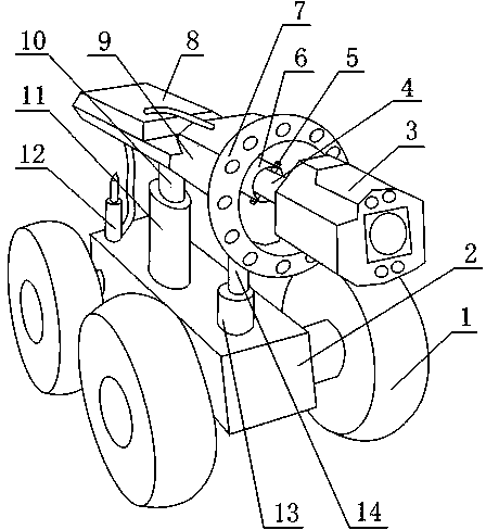
[0014] like figure 1 As shown, a detection device includes a control box 2, an image acquisition system is arranged above the control box 2, a hydraulic device is arranged between the image acquisition system and the control box 2, and the two ends of the hydraulic device are respectively connected to the image Acquisition system is connected with control box 2; Described image acquisition system comprises camera 3, the fixed platform 9 that is connected with camera 3, camera 3 is connected with control box 2, is provided with sleeve 6 between fixed platform 9 and camera 3, sleeve One end of 6 is fixed to the fixed table 9, and the other end of the sleeve 6 is provided with a drum 4, which is fixed to the camera 3, and a pin 5 is arranged in the drum 4, and the pin 5 passes through the drum 4 and the sleeve at the same time 6, and the drum 4 can rotate around the pin shaft 5, the hydraulic device includes two hydraulic cylinders, the hydraulic cylinders are connected to the co...

Embodiment 2

[0017] like figure 1 As shown, an image acquisition card is arranged inside the fixed table 9, and a data line is arranged on the fixed table. One end of the data line passes through the sleeve 6 and the rotating drum 4 and is connected to the camera 3, and the other end is connected to the image acquisition card. Frame acquisition card, also known as image capture card, is a hardware device that can acquire digital video image information, store and play it out. Many frame grabbers can obtain accompanying sound while capturing video information, so that the audio part and video part can be stored and played synchronously during digitization. It is an essential hardware device for our image processing. Through it, we can transfer the video signal captured by the camera from the video tape to the computer, and use the relevant video editing software to edit the digital video signal. Processing, such as cutting pictures, adding filters, subtitles and sound effects, setting tran...


PUM


Abstract

The invention discloses detection equipment. According to the equipment, an image collecting system is arranged above a control box; a hydraulic device is arranged between the image collecting system and the control box; a camera is connected with the control box; a sleeve is arranged between a fixing station and the camera; one end of the sleeve is fixed with the fixing station; a rotary drum is arranged in the other end of the sleeve and fixed with the camera; a pin shaft is arranged in the rotary drum and simultaneously penetrates through the rotary drum and the sleeve; the hydraulic device comprises two hydraulic cylinders which are connected with the control box; a piston rod is arranged in each hydraulic cylinder; one ends, far away from the hydraulic cylinders, of the piston rods are respectively fixed with the fixing station and the camera. The equipment has the advantages that the equipment is put into a pipeline to shoot the inner wall of the pipeline so that operating personnel can conveniently know the concrete structure of the inner wall of the pipeline to adopt corresponding processing means, thus the problem that in the existing petroleum pipeline detection process, the concrete structure of the inner wall of the pipeline cannot be known by adopting a microwave flaw detection way is solved.

Description

technical field [0001] The invention relates to a device, in particular to a detection device, which belongs to the field of oil pipeline detection. Background technique [0002] Petroleum, also known as crude oil, is a viscous, dark brown (sometimes greenish) liquid. There are oil reserves in parts of the upper crust. It is composed of a mixture of different hydrocarbons, and its main component is alkanes. In addition, petroleum also contains elements such as sulfur, oxygen, nitrogen, phosphorus, and vanadium. Petroleum is mainly used as fuel oil and gasoline, which constitute one of the most important primary energy sources in the world. Petroleum is also a raw material for many chemical industry products such as solutions, fertilizers, pesticides and plastics. Oil is mostly hydrocarbons. It is composed of a mixture of different hydrocarbons. The chemical elements that make up petroleum are mainly carbon (83% ~ 87%), hydrogen (11% ~ 14%), and the rest are sulfur (0.06%...

Claims


Application Information

Patent Timeline
Patent Type & Authority Applications(China)
IPC IPC(8): G01N21/84G01N21/88
Inventor 贺昶明
Owner CHENGDU ZHIRONG ZHICHUANG INTPROP MANAGEMENT CO LTD
Learn More